Download
1 / 21
580 likes | 1.06k Views
“Linear Gap” New Capability Seminar October 2001. Linear Gaps. What is a “linear gap”? Why do I want linear gaps? What is theory/implementation? Patran interface Examples Limitations Conclusions. P = 30 lbs. Y. Node 2. X. Node 1. U init. U gap. What is a “linear gap”?.

E N D
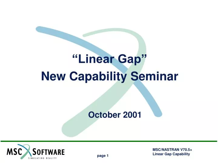
“Linear Gap” New Capability Seminar October 2001
Linear Gaps • What is a “linear gap”? • Why do I want linear gaps? • What is theory/implementation? • Patran interface • Examples • Limitations • Conclusions
P = 30 lbs. Y Node 2 X Node 1 Uinit Ugap What is a “linear gap”? • The linear gap is a contact element in its simplest form: • DOF-to-DOF gaps with initial openings • Linear, therefore does not include: • friction • large displacements • material non-linearity Uses iterative solver to determine open/closed status. Node 3
Why do I want linear gaps? • Successful analysis will use proper boundary conditions and load paths. • Linear gaps can solve a large class of problems • Heel-toe interaction • Hole bearing • Simple contacts • Bridge Supports • Fitting contacts • Efficient when compared to nonlinear methods
Theory / Implementation • The linear gaps provide for simple contact, (compressive) forces only. • MPC’s are used to define the gaps • The displacements and mpcforces are used to determine if each gap is “welded” or “free” • Displacement criteria: no penetration (MPC displacement >=0) • MPCFORCE criteria: compressive force only (MPCforce <=0) • An iterative procedure is used to solve the model based on displacements/mpcforces
Uy (opening) Uy (closing) Uy (initial) Y Opening Grid Uyopening - positive disp will open the gap Closing Grid Uyclosing - positive disp will close the gap Initial Opening Uyinitial - initial separation between grids The equation for the gap displacement can be written as: Uygap = Uyopening - Uyclosing + Uyinitial Rearranging in MPC format and setting Uyclosing as the dependant (first) term: Uyclosing - Uyopening + Uygap - Uyinitial = 0 X P = 30 lbs. Y Node 2 X Node 1 Uinit Ugap Node 3
Theory / Implementation • SPOINTs are defined for Ugap and Uinit SPOINT 55 155 • SUPORT puts SPOINT 55 (Ugap) in the R-set for iteration. SUPORT 55 0 • SPC defines initial gap opening =.05 (Uinit) SPC 101106 155 0 .05 • MPC Entry: (Eq. of motion: Uy3 - Uy2 + Ugap - Uinit = 0) $ SID G1 C1 A1 G2 C2 A2 MPC 101106 3 2 1.0 2 2 -1.0 $ G3 C3 A3 G4 C4 A4 55 0 1.0 155 0 -1.0
MSC.Patran Interface • PCL Utility developed to easily create linear gaps and write appropriate MSC.Nastran input entries. • Easy Creation/Deletion of linear gaps • Useful graphics for visualization • Special Verification • Creates complete, run-ready, MSC.Nastran job • Stores gaps on MSC.Patran db • Session file support
CREATING GAPS Initial Assumption: Opened or Closed Special Cases Initial opening defined by nodal distance (automatically calculated) or by user specified value Create gaps within tolerance; if coincident nodes identify the opening node based on Node ID Select Nodes (and direction) on both sides of gap, interface will automatically determine “Opening” and “Closing” Nodes and check for SPC/MPC conflicts
CREATING GAPS Initial Assumption: Opened or Closed Initial opening defined by nodal distance (automatically calculated) or by user specified value User defines “Opening” Node(s), “Closing” Node(s), and directions.
VISUALIZING GAPS Gap Display: No Options (0.15) (0.15-S) (-S) Gap Display: All Options
VERIFYING GAPS If any LBC (SPC’s) have been added during the session, “Reload” the form and select appropriate boundary conditions “Rechecks” any model changes related to MPC and/or SPC changes (MPC’s include RBAR, RBE2, RBE3, etc.)
L-Bracket Heel-Toe Analysis 100 Pounds 0.25” Thick Aluminum 3.0” Shear Bolt = .248 Diameter Shear Hole= .250 Diameter Linear gaps defined in radial direction to distribute bearing load 1.0” 2.0” Tension Bolt: 0.5 inches long, .250 Diameter, attached to plate with RBE3 and fixed at bottom “Gap to Ground” along bottom surface
Local Stress Distribution Force Transfer at Shear Bolt Local Stress Distribution Force Transfer at Tension Bolt
Interference Fit Interference Gaps: Opening node is plate Closing node is pin Initial Gap determined by nodal distance Plate 5 X 4 X .1 .500 hole .40 from edge Pin .506 dia X .1 thick (All Aluminum)
Non-uniform force distribution caused by edge effect
Limitations • Remember “simple gaps” only • NO LARGE DISPLACEMENTS • NO FRICTION • NO MATERIAL NONLINEARITY • Otherwise use SOL 106 with CGAP/PGAP • with or without PARAM,LGDISP • with or without MATS1 • etc.
Additional Information • MSC.Nastran V70.5 Release Guide; Section 3.5, download from: http://www.mechsolutions.com/support/documentation/index.html • McCullough, John and Proctor, Lance, “LOCAL ANALYSIS OF FASTENER HOLES USING THE LINEAR GAP TECHNOLOGY OF MSC/NASTRAN,” 1999 MSC Aerospace Users’ Conference. Download from:http://www.mechsolutions.com/support/library/auc99/
Conclusion • Simple gap contact is available in SOL 101 of MSC.NASTRAN V70.5 or later. • Constrained Displacement ITERative technique (CDITER). • Simple gaps -- no friction • Works with large models • Reduces the complexities inherent with SOL 106 (gap stiffness, convergence, etc.) • Allows use of GPFORCE (now available in SOL 106 in V2001) • Used in instances where non linearity's do not exist, but contact is required.