Download
1 / 19
190 likes | 199 Views
This study focuses on the metrology and trimming of CCD detector height to meet optical requirements. The process involves measurements, analysis, and adjustments using specialized equipment. The results demonstrate the effectiveness of the metrology process and the impact of environmental factors on measurements.

E N D
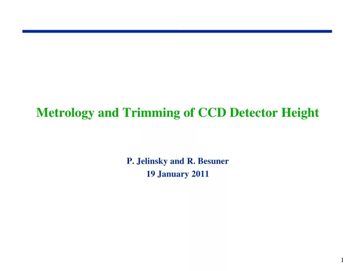
Metrology and Trimming of CCD Detector Height P. Jelinsky and R. Besuner 19 January 2011
Background • Instrument optical requirements: • Detector Active area flat to ±0.005mm (10 µm P-V) • Each detector: 15.000±0.005mm above mounting surface on its own. • Detector active areas 15.000mm above cold plate (±0.010mm …including cold plate effects) • Detectors are packaged as close as practical to above req’ts. • But they still have residual tilts and piston. • So after fabrication, do metrology and trim height and tilts of each detector.
Packaged CCD, showing 2mm molybdenum spacers Spacer ‘B’ Spacer ‘C’ Spacer ‘A’ • Late in the design the substrate was reconfigured which increased the detector height to 15.050 mm with the nominal spacers.
Metrology Apparatus in 77 Cleanroom, NIR Det in place 3x 15.240mm thick ceramic gauge blocks 2x Keyence distance-measurement devices (obscured) Reference flat NIR Detector on 2mm spacers Polymeric pad (since replaced with electrically grounded pad) Y-stage X-stage Granite block
Metrology Apparatus in 77 Cleanroom, CCD in place Cable-management tower
Metrology Apparatus Operation • Turn on Keyence devices, and allow >2 hours of warm-up (see warm-up chart below). • Install detector on Metrology Apparatus. • Enclose Metrology Apparatus in tent (to limit convection, see later slide). • Operate Metrology Device using Metrology Software and specialized script. • 8 measurements per gauge block, at beginning, end, and intermediate times during metrology (accounts for some drift, see later slide). • Measurements every 0.5mm on detector surface, 5625 points on active area. • Takes 3-4 hours. • Crunch data to determine piston, tilt, and deviation from a plane. • Replace precision Molybdenum spacers with spacers of slightly different thickness to trim detector. • Repeat metrology and piston/tilt analysis to verify and document that req’ts are met. Warm Up
Keyence device linearity • Keyence performance spec’s w.r.t. linearity is 0.02% of range or 9µm. • We want to verify that relative measurements over ranges from microns to 100’s of microns are accurate to better than 1um. • Use precision ‘stepmaster’ temporarily mounted to an NIR pedestal to estimate true linearity of Keyence devices (accurate to ±0.2µm). • Result: All step sizes were measured within 0.4um of labeled step sizes.
Metrology Apparatus drift over time scale of detector measurements • Took readings of gauge blocks repeatedly over about 4 hours. (Detector measurement takes ~3hr). • We see similar trends in the gauge block data taken during detector metrology. • Maybe a thermostat or humidifier kicking on or off in clean room. • During detector measurements, take gauge block measurements at beginning, end and three times in between. • Use that data as an offset to detector measurements, linearly interpolating over time (we refer to this as ‘Time Correction’)
CCD 017 before shimming • Left is not time-corrected, right is same data with time-correction. • Data is mm above mounting surface.
Changes required to spacer thickness • The data crunching indicates that to reach 15.05mm we want to add 1.5um to spacer A, 2.5um to spacer B, 7um to spacer C. • Measure old spacers (moving forward, we will always use 3 spacers that are cherry-picked to be identical to each other.) • Old spacer A=2.0025mm • Old spacer B=2.0045mm • Old spacer C=2.003mm • Since we do not have an infinite number of different-thickness spacers, we had to choose a different target height for this exercise. • Moving forward, we will need a variety of thicknesses. • Might make sense to take measurements of all detectors first, then specify spacers we need rather than inventory many hundreds of spacers. • So we aimed for 15.039mm, which we could theoretically hit with spacers we actually possess. • New spacer A=1.993mm • New spacer B=1.996mm • New spacer C=1.999mm
CCD017 after shimming, first measurement • This is time-corrected data • Horizontal blue ‘feature’ seems to be on a time-scale too small to have been captured by the intermediate gauge block measurements. • The scan pattern is row by row, right to left, starting at the top.
To cut down convection effects, fashion a ‘tent’ over the apparatus
After shimming, before and after installing tent • Horizontal Blue ‘feature’ goes away. • Data are visibly less noisy-appearing when the tent is used. Is this line real? Seems possible.
Repeat gauge block drift measurement under tent • These are separate measurements on different days, presumable in different parts of clean room HVAC cycling. • Again, tented data appear less noisy. • Not sure what that feature is in both sets right at the beginning. Elapsed time (h)
New data, on shims (not a best-fit plane), compared with old vision-machine data (residual to best-fit plane) • Note three persistent dust-induced indentations. • A significant difference between the old and new data: • In old data, bolts were torqued as lightly as could be managed. • In new data, bolts were torqued to flight levels (10 lbf-in) Bolt locations
The bottom line • Mean height after shimming is 15.038mm, target was 15.039mm. • P-V distortions are 4.2um relative to target plane. This yellow point was an outlier that was thrown out. Inspection revealed a piece of lint here.
Conclusion • This demonstration was successful. • Document 1066 (Detector Height Trimming Procedure, already written) will be the released procedure. • Can be used on future detectors and small focal planes (up to 150mm Ø) by replacing the part on which the detector mounts…for example: • 4k X 4k (62 x 62mm), 2k X 4k (31 x 62mm) CCD’s • 4k X 4k H4RG (62 x 62mm) • ASTrO focal plane (4 H2RG) (73 x 73 mm) PART TO REPLACE Gauge Block Mounts Detector Mount