Download
1 / 7
70 likes | 203 Views
THEMIS INSTRUMENT TRAINING FGM. Overview. Introduction FGM stands for Fluxgate Magnetometer. Measures DC to 10Hz Magnetic fields. The sensor is situated at the end of a 2m boom that is deployed early on in the mission.

E N D
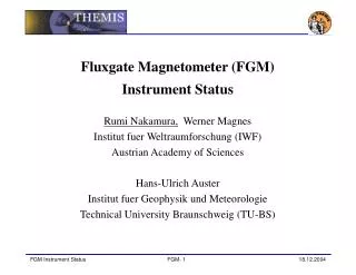
Overview • Introduction • FGM stands for Fluxgate Magnetometer. • Measures DC to 10Hz Magnetic fields. • The sensor is situated at the end of a 2m boom that is deployed early on in the mission. • The sensor is a miniature version similar to a variety of sensors flown on many space missions. • The electronics makes use of processing in the digital domain to reduce noise. • Keeping the spacecraft free from large magnetic fields is one of the major challenges of Themis.
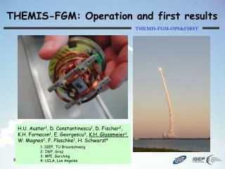
FGM Operation The FGM Sensor contains two ring cores made from magnetically permable material. Around these cores, wires is wound in which a 8kHz square wave is driven. This drives the ring core material into magnetic saturation. Another set of wire is wound around the ring cores that picks up the field produced by the ring cores response to the excitation signal. The external magnetic environment affects how the ring core material responds to the excitation and this consequently affects the pick up current. Fluxgates work best as null field sensors so a feedback current is calculated from the pick up current to keep the sensors in a zero field. The amount of current to keep the sensor nulled is proportional to the external magnetic field.
FGM ITOS Page FGM has a number of test modes. For normal science operations, the FGM should be configured as shown. If these do not say OK then there is an interface problem with the FGM. FGM Range can be changed from 0 to 8. 0 is the widest range ±32,000nT, 8 is the narrowest ±125nT. FGM low rate TLM can be commanded to different rates – 4Hz to 128Hz Mag Boom actuation – repeated on Actuator Page
FGM Telemetry • FGM produces four types of telemetry. • APID 405 – used for attitude control. 8Hz produced and sent in VC1 data. Controlled by the IFGEENABLE command. Enabled during manouvers. • APID 410 – Spin fits. Calculated by FSW. Enabled during Slow and Fast Survey. • APID 460 – Low speed science data. 4Hz to 128Hz. Enabled during Fast Survey. • APID 461 – High speed science data. 128Hz. Enabled during Particle Burst.
FGM Commands • Each FGM model has a default set of commands that are uploaded on power on specific for that unit. It is unlikely that these will change much on orbit, however from time to time it maybe necessary to modify the command set.