Download
1 / 43
450 likes | 1.44k Views
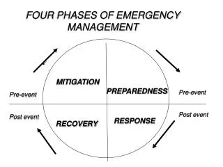
AC Mitigation Overview. Mike Tachick Dairyland Electrical Industries, Inc. Mitigation requirements. Connection to low impedance grounding DC isolation of CP system Addressing lightning, AC faults Complying with codes. AC Power Effects. Steady-state induction Can be measured

E N D
AC Mitigation Overview Mike Tachick Dairyland Electrical Industries, Inc.
Mitigation requirements • Connection to low impedance grounding • DC isolation of CP system • Addressing lightning, AC faults • Complying with codes
AC Power Effects • Steady-state induction • Can be measured • Fault current/voltage • Usually estimated/modeled • Conductors, grounds sized for estimated fault current
Background: AC and Lightning Compared Amplitude Time (milliseconds) Time (microseconds) Alternating Current Lightning
AC Voltage Mitigation • Create a low impedance AC path to ground • Have no detrimental effect on the CP system • Provide safety during abnormal conditions (AC fault, lightning)
Factors Affecting Mitigation Key Factors… • Soil resistivities, layers • Proximity to power lines • Power line loading • Quality of pipeline coating …and many others
AC Mitigation Design • Best performed by consulting engineers using specialized software • Evaluates coating stress, step and touch potentials, fault current, steady-state current, grounding arrangements, etc. • Typical for larger projects, new construction
AC Mitigation Design • CP personnel can roughly estimate or experiment • Practical for small projects, single locations • Trade-off: optimizing design vs. efficiently installing estimated requirements
AC Mitigation Design • Induced voltage is ongoing nuisance • AC faults are significant risk • Design should consider lightning hazards • Control step and touch potentials
Typical Field Values • Open circuit voltage: up to 50V • Short circuit current: up to 30A Can exceed these values
Field Measurements • Open circuit voltage: voltmeter from pipe to grounding system • Short circuit current: AC ammeter – reads current in a bond between pipe and ground
Mitigation Example Problem: • Open-circuit induced AC on a pipeline = 40 V • Short-circuit current = 15 A • Then, source impedance:R(source) = 40/15 = 2.7 ohms Solution: • Connect pipeline to ground through decoupler
Mitigation Example • Typical decoupler impedance:X = 0.01 ohms0.01 ohms << 2.7 ohm source 15A shorted = 15A with decoupler • V(pipeline-to-ground) = I . X = 0.15 volts • Result: Induced AC on pipeline reduced from 40 V to 0.15 V
Local Mitigation • Reduces pipeline potentials at a specific point (typ. accessible locations) • Commonly uses existing grounding systems • Needs decoupling
High Voltage on Pipeline Low Local Mitigation
Continuous Mitigation • Reduces pipeline potentials at all locations • Provides fairly uniform over-voltage protection • Typically requires design by specialists
Continuous Mitigation Gradient control wire choices: • Zinc ribbon • Copper wire • Not tower foundations!
Reasons to DC Decouple From Grounding Systems If not decoupled, then: • CP system attempts to protect grounding system • CP coverage area reduced • CP current requirements increased • CP voltage may not be adequate But simultaneous AC grounding is also needed…
Decoupler Characteristics • High impedance to DC current • Low impedance to AC current • Passes induced AC current • Rated for lightning and AC fault current • Fail-safe construction • Third-party listed to meet electrical codes
Typical Decoupler Ratings • Threshold: 2-3V peak • AC impedance: 0.01Ω • DC leakage: <<1mA @ 1V • AC fault: 2 to 10kA • Lightning: 75-100kA
Zinc Ribbon for Mitigation • Provides CP if not isolated • Affects CP if impressed current system is used • Doesn’t allow instant-off readings when not isolated • Grounding effectiveness changes with zinc consumption • Can pick up stray currents
Copper for Mitigation • Common, low cost material • Must be decoupled with suitable device
Grounding Materials If decoupled… • CP system not affected • Allows instant-off readings • Lengthens grounding system life • Avoids stray current pick up
Other Grounds • Casings at road crossings • Station grounding system • Existing metallic vault • Abandoned pipeline • Culvert • Other metallic structure with low resistance to earth
Mitigation - Other Issues • Risks at insulated joints • Other affected facilities • Hazardous locations
Mitigating at an Insulated Joint • Provides AC mitigation for pipeline • Provides over-voltage protection for insulated joint • Easy location to test, install
Other Affected Facilities • Transfer of AC fault conditions to other structures • Goal is to keep voltage from rising, control current flow • Doesn’t mean that current will not get on your pipeline or others • Accomplished by bonding, grounding
Example site Metering Station Road Casing I J Power line Substation Pipeline I J
Example site Metering Station Road Casing I J Power line Substation Pipeline I J
Hazardous Locations • Accomplish mitigation while complying with codes • Determine your site classification • Use certified (listed) products and methods • Keep conductors short to limit over-voltage, possible arcing, due to lightning
Hazardous Locations • CFR 192.467 – combustible atmospheres and insulated joints • CFR 192 incorporates the National Electrical Code “by reference” • NEC defines hazardous locations and product requirements
Questions? • For follow up questions: mike@dairyland.com