Download
1 / 34
360 likes | 373 Views
Variable Speed System Pumping. Theory & application “Why would I use one of these things?. Why Use a Variable Speed Circulator?. Good question… What do they do? Vary speed based on changing loads Use external information Best applications… System circulator with zone valves

E N D
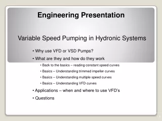
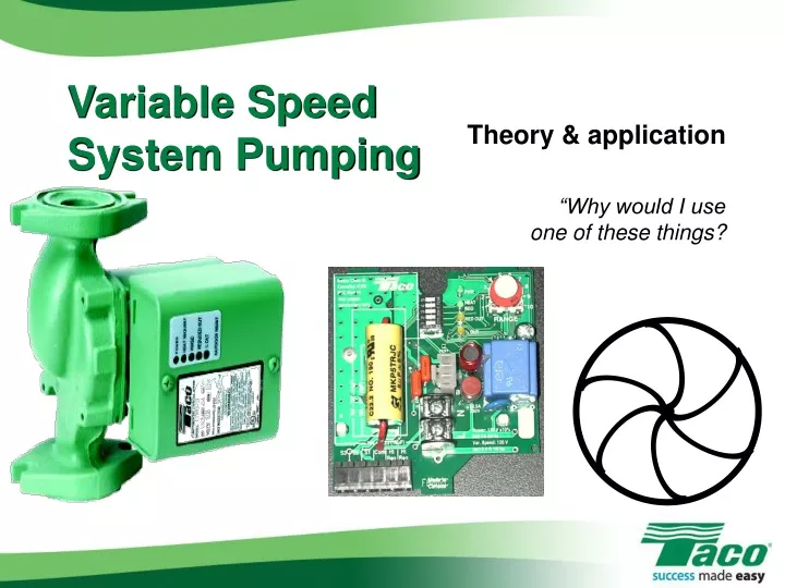
Variable Speed System Pumping Theory & application “Why would I use one of these things?
Why Use a Variable Speed Circulator? • Good question… • What do they do? • Vary speed based on changing loads • Use external information • Best applications… • System circulator with zone valves • Radiant with multiple zoneson single manifold using actuators
Universal Hydronics Formula • GPM = BTUH ¸DT x 500 • GPM = Gallons per minute • BTUH = Heating load • DT = Design temperature drop • 200 for baseboard • 100 for radiant • 500 = 8.33 x 60 x 1
Sample Project • Heat loss = 75,000 BTUH • Design temp = 00 • 3 zones fin tube • 25K BTUH each • 200DT
Do The Math! • GPM = BTUH ¸DT x 500 • GPM = 75,000 • GPM = 75,000 • GPM = 7.5 20 x 500 10,000
For Each Zone… • 25,000 BTUH each • GPM = 25,000 • GPM = 25,000 • GPM = 2.5 per zone 20 x 500 10,000
Pipe Sizing • 2-4 GPM = ¾” pipe • 4-8/9 GPM = 1” pipe • 8/9-14 GPM = 1¼” pipe • 14-22 GPM = 1½” pipe • Min/max velocity • 2-4 FPS • > 4 = velocity noise
¾” 1” Let’s Pipe ‘Er Up!
Head Loss 150’, including element
Head Loss • Longest run = 150’, including element • Multiply by 1.5 to allow for fittings, etc • 150 x 1.5 = 225’ • Multiply by .04 • 4’ head/100’ of pipe • 225 x .04 = 9’ head loss • 7.5 GPM @ 9’ head
15 10 5 5 20 10 15 Pick The Pump… Taco 008 Pump Curve 9’ Head 7.5 GPM
15 10 5 5 20 10 15 System Curve System Operating Point – All Zones Calling
15 15 10 10 5 5 5 5 20 20 10 10 15 15 As Zone Valves Close… System Operating Point – 2 Zones Calling System Operating Point – 1 Zone Calling 4 GPM 6.5 GPM
GPM = BTUH 6.5 = 50,000 DT is lower than design Poor heat transfer Less efficient boiler Velocity noise 15 10 5 5 20 10 15 As Zone Valves Close… System Operating Point – 2 Zones Calling DT x 500 DT x 500 DT 6.5 GPM
So What Do We Do About It? • Ignore it? • “That’s just the way these systems are!”
15 System Operating Point – All Zones Calling 10 5 5 20 10 15 A Better Solution… • Variable speed pumping! Actual flow rate » 9 GPM
GPM = BTUH BTUH = GPM x DT x 500 DT = BTUH DT = 75,000 DT = 160 DT w/2 zones = 150 DT w/1 zone = 120 Under DESIGN conditions! ¸ 500 ¸ 500 GPM 9 Universal Hydronic Formula DT x 500
But What If DT Was Fixed? • GPM = BTUH • GPM = 75,000 • GPM = 7.5 • The flow will vary! DT x 500 = 50,000 = 25,000 DT x 500 20 5 2.5
15 10 5 5 20 10 15 A Better Solution…
An Important Consideration… • Calculate max flow rate • Estimate head loss • Length X 1.5 X .04 • Head loss at MAX flow rate • Actual flow rate much less • Can overestimate head by 50% • DT circulator “self-adjusts”
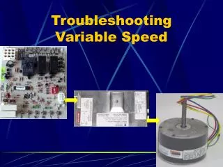
Taco 00-VDT • Variable speed DT circulator • Control built in • Simple to install • Simple to program • Simple to understand! • 008, 0012, 0013 VDT
A Simple Solution 00-VDT
Setting It Up… • Dip Switches • Switch 1, 3 ON • All others OFF • Range Dial • Adjust to desired DT
Supply Sensor Supply Sensor Return Sensor Return Sensor Wiring It Up… • H-N to ZVC • Supply sensor to S2 & Com • Return sensorto S1 & Com
Delta T vs. Delta P • ΔT directly related to flow rate • Pump speed adjusts to required BTU/hr • GPM = BTUH/ ΔT x 500 • ΔT always runs at lowest required speed • Delta P adjusts only to pressure change • Needs accurate head loss calculation – not estimation • Doesn’t know which zones are open/closed • May not be able to satisfy heat demand
36 33 Energy Consumption 137 kW kW consumed, 2,500 hour heating season Assuming 12.5 hours of operation daily 117 kW 102 kW ECM circulators draw constant 5 kW in “standby” mode to keep memory powered – for 6,260 non-heating hours annually Taco 00 VDT draws NO powerwhen off – runs off standard relay or zone valve controller
25% Savings!! WOW!!!! Dude, that’sonly $3.16 per year… Cold, Hard Facts…
What About System Efficiency? • Big difference between Delta T & Delta P • Cast iron boilers • Delta T circulator controls return water temperature • Reduces short cycling • Uses less fuel • Bigger impact with “mod-con”
Some Parting Thoughts… • ΔT directly related to flow rate • Pump speed adjusts to required BTU/hr • ΔT ensures optimum performance of BB, radiant, etc • ΔT does not “flat line” • ΔT always runs at lowest required speed • Lots of models • EASY to set up!