Download

1 / 20
200 likes | 312 Views
G. Kocsis 1) A. Alonso 2) , B. Alper 3) , G. Arnoux 3) , J. Figueiredo 4) , D. Frigione 5) , L. Garzotti 3) , M. Lampert 1) , P.T. Lang 6) , G. Petravich 1) , R. Wenninger 6) 1) KFKI RMKI, EURATOM Association, P.O.Box 49, H-1525 Budapest-114, Hungary

E N D
G. Kocsis1) A. Alonso2) , B. Alper3), G. Arnoux3), J. Figueiredo4) , D. Frigione5) , L. Garzotti3) , M. Lampert1), P.T. Lang6),G. Petravich1), R. Wenninger6) 1) KFKI RMKI, EURATOM Association, P.O.Box 49, H-1525 Budapest-114, Hungary 2) Laboratorio Nacional de Fusion, Euratom-CIEMAT, 28040 Madrid, Spain 3) Euratom/CCFE Association, Culham Science Centre, Abingdon, Oxon, OX14 3DB, UK 4) Assocoation EURATOM-IST, Av. Rovisco Pais, 1049-001 Lisbon, Portugal 5) Associazione EURATOM-ENEA sulla Fusione, CP 65, Frascati, Rome, Italy 6) MPI für Plasmaphysik, EURATOM Association, Boltzmannstrasse 2., D-85748 Garching, Germany Comparison of the onset of pellet triggered and spontaneous ELMs G. Kocsis, p1
Outline Introduction: ♠pellet pacemaking ♠radial localisation of pellets at ELM trigger ♠possible seed perturbation of ELM trigger Pellet ELM triggering investigation on JET: ♠ experimental set-up ♠ data processing ♠ comparison of the onset of filamentary structures for pellet triggered and spontaneous ELMs Summary and outlook G. Kocsis, p2
Pellet ELM pacemaking Injection of frequent small and shallow penetrating cryogenic pellets has been found a promising technique to mitigate ELM effect. The technique works but the underlying physical processes of the ELM triggering are not well understood. Therefore the aim is to study where and how a pellet triggers an ELM to be ableto make predictions for future machines and to optimise the pellet pacing tool. G. Kocsis, p3
pedestal Radial localization of the pellet at onset of the triggered ELM for ASDEX Upgrade PELLET 500 ms separatrix crossing time Ablation monitor Pick-up coil + ELM-delay ELM onset time B31-14 ELM (type-I) Consistently with peeling-ballooning model of the ELM predicting instability onset localized to the pedestal steep gradient region Only 5-15% of the expected pellet mass is ablated until the position of the seed perturb. Data from DIII-D also indicates that the pellet triggers an ELM before the pellet reaches half way up the pedestal G. Kocsis, p4
Possible seed perturbation of pellet ELM triggerring Pellet injection According to the observation on ASDEX Upgrade ♠ the localized high pressure pellet cloud elongated along the field line ♠ the axisymmetric plasma cooling have been recognized as candidate perturbation for trigger mechanism. G. Kocsis, p5
Pellet ELM triggering investigation on JET:comparison of the onset of filamentary structures for pellet triggered and spontaneous ELMs The pellet ELM triggering was studied on JET using fuelling size pellets The onset of spontaneous and triggered ELM was investigated by comparing the onset measured by ♠ magnetic coils: MHD ELM onset ♠fast framing camera diagnostics: bright spots on plasma facing components caused by the interaction of ELM filament with limiters G. Kocsis, p6
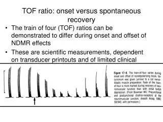
ELM onset determination using magnetic diagnostic Several Mirnov coils were used ELM: high frequency quasi periodic oscillation on Mirnov coil signals Bandpower of 100-300kHz was calculated which was taken as magnitude of the ELM related MHD activity An appropriate threshold was used to determine the onset on each signal The earliest of the onset times of the individual signals were selected as MHD ELM onset time. MHD ELM onset Div Hα G. Kocsis, p7
JET fast framing camera observation geometry LFS pellet injection View: full poloidal cross section covering 90 degrees toidally and seeing the plasma facing components (limiters) on the outboard wall. The cross section of the LFS pellet injection falls into the middle of the view. Time resolution: 10-15μs G. Kocsis, p8
Fast framing camera: typical ROIs Inter limiter box Limiter box 1 2 3 4 5 6 7 7 2 3 4 5 6 1 pellet box EFIT, #76930, t=58.919s Model image of some plasma facing elements Fast framing image over plotted on slow framing image Max. 70kframe/s, 14μs 128x 128 pixels pellet + ELM fast dynamics Max. 18kframe/s, 56μs 320 x 384 pixels divertor + pellet +ELM Max. 30 kframe/s, 33μs 240 x 256 pixels Part of the divertor + pellet + ELM G. Kocsis, p9
Hot spot observation during spontaneous ELM 1 1 1 1 1 1 2 2 2 2 2 2 3 3 3 3 3 3 4 4 4 4 4 4 5 5 5 5 5 5 6 6 6 6 6 6 7 7 7 7 7 7 I1 I2 I3 First bright spot ~100μs I4 I5 I6 Filament G. Kocsis, p10
Filament observation during ELM trigger for LFS pellet injection I1 I2 I3 pellet 1 2 3 4 5 6 7 7 2 3 4 5 6 1 2 3 4 5 6 7 1 I4 I5 I6 1 2 3 4 5 6 7 1 2 3 4 5 6 7 1 2 3 4 5 6 7 filament G. Kocsis, p11
Image processing to reveal features of the bright spots Inter limiter box Limiter box 2 3 4 5 6 7 1 pellet box Limiter box Inter limiter box 3 2 1 4 5 6 7 Pellet box 1st step 2nd step Images were spatially calibrated: The bright spots are on wall elements calibration possible from one view for each pixel the poloidal and toroidal angle of the wall element seen is calculated 7 6 5 4 3 2 1 G. Kocsis, p12
Image processing to reveal features of the bright spots 2nd step 3rd step 7 6 5 5 5 3 3 4 3 2 2 2 1 1 1 G. Kocsis, p13
Comparison of spontaneous and triggered ELM footprints Box 1 Box 3 Box 1 #76930 #76997 Box 3 spot stops spot stops Bright spot moves up G. Kocsis, p14
Comparison of first appearance of bright spots for triggeredand spontaneous ELM 1 2 3 5 From the ‘box radiations’ the poloidal location of the maximum radiation was calculated as a function of time. The poloidal location of the first (early) appearance (onset) of the bright spots are plotted as a function of time elapsed after the MHD ELM onset for triggered (◊)and spontaneous (+) ELMs The triggered ones are around the MHD ELM onset The spontaneous ones are [0,100]μs after the MHD ELM onset The location for spontaneous ELMs has a larger scatter, but both cases are around the mid plane G. Kocsis, p15
Localisation of the seed perturbation for LFS pellets Natural type-I ELM (100-200kJ) Pellet triggered type-I ELM (100-200kJ) Plasma wall interaction footprint evolution is less regular Plasma wall interaction footprint evolution is more regular No delay relative to magnetic ELM onset Up to 100 μs delay relative to magnetic ELM onset The seed perturbation for the ELM triggering may be the pellet cloud The ELM is probably born at the location of the pellet ablation This conclusion is confirmed at DIII-D ( exp. in January, 2010), too. (L. Baylor) Accordingly for LFS pellet ELM triggering the interaction of the filaments are immediately observable. For spontaneous ELMs filaments may born at arbitrary toroidal location and need time to reach the camera observation volume.
V H L Summary and outlook Pellet ELM triggering investigation on JET:comparison of the onset of filamentary structures for pellet triggered and spontaneous ELMs was performed For LFS fuelling size pellets the high pressure pellet cloud formed around the pellet seems to be the seed perturbation Initial nonlinear MHD simulation for pellet ELM triggering shows destabilization of medium-n ballooning modes. High pressure in pellet plasmoid drives MHD instability forming a single helical perturbation at the pellet position for LFS injected pellets, which agrees with the observations on JET Huysmans, EPS 2009 Future plans: The present number of investigated triggered events is low, therefore evaluation of more pellet triggered ELMs is foreseen Investigation of VHFS pellet ELM triggering (only in new campaigns, 2011-) Reduction of the pellet size (only in new campaigns, 2011-) G. Kocsis, p17
Type-I ELMy H-mode el. diam. Drift, n>0 ion diam. Drift n<0 delayed triggered Prompt triggered 15 pellet induced ELMs have been analysed for their basic poloidal/toroidal structure. The single, upward rotating structure represents a rather specific case. Typically, two or more such pronounced structures occur simultaneously. Despite the fixed pellet launch position, they appear initially at a more or less random toroidal position relative to the pellet, i.e. they are not directly growing out of the pellet plasmoid. washboard-type precursor mode slowing down, n=4 No precursor Neuhauser et al, NF, 48, 045005, 2008