Download
1 / 50
500 likes | 512 Views
WANs and Routers. Introduction to WANs. A wide-area network (WAN) is a data communications network spanning a large geographic area such as a state, province, or country. Use transmission facilities provided by common carriers, for example, telephone companies.

E N D
Introduction to WANs • A wide-area network (WAN) is a data communications network spanning a large geographic area such as a state, province, or country. • Use transmission facilities provided by common carriers, for example, telephone companies. • It interconnects LANs that are usually separated by large geographic areas. • Operates at the physical layer and the data link layer of the OSI reference model (Typically) • See next slide
WAN Layers • The WAN physical layer describes the interface (electrical, mechanical, operational, and functional) between the data terminal equipment (DTE) and the data circuit-terminating equipment (DCE). Typically, the DCE is the service provider and the DTE is the attached device. • The WAN data link layer protocols describe how frames are carried between systems on a single data link. They include protocols designed to operate over dedicated point-to-point, multipoint, and multi-access switched services such as Frame Relay
DCE/DTE Interfaces • DCE - Data Carrier Equipment • A modem interfaces to the outside carrier (Telco) equipment • It is the circuit terminating equipment • The DCE typically provides the serial clock signal • DTE – Data Terminal Equipment • The Router interfaces to the terminal equipment (user devices)
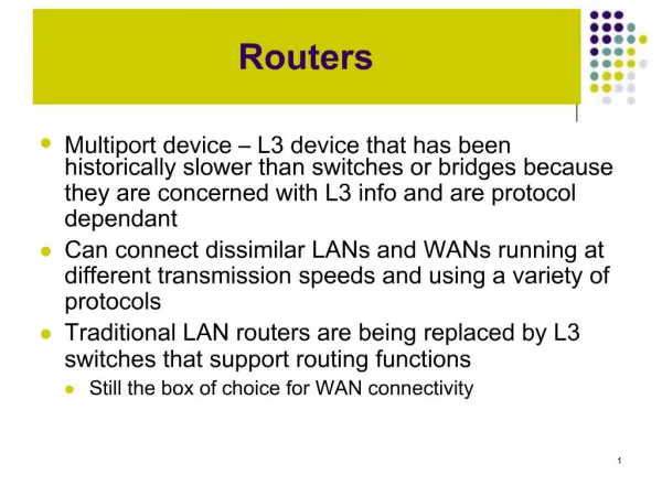
WAN Devices • Routers • route between networks (LANS) • Provide slow speed serial WAN interfaces • Switches in the WAN • provide connectivity for voice, data, and video • Modems • Interface to voice-grade services • Analogue modems • Interface to digital services • Channel service units/digital service units (CSU/DSUs) • Communication servers • concentrate dial-in and dial-out user communication.
Network Layer Path Determination • The two main functions of routers are • selection of best paths for incoming data packets, • switching packets to the proper outgoing interface. • Routers accomplish this by building routing tables and then exchanging their routing tables with other routers. • Routing tables can configured manually • But generally they are maintained dynamically by using a routing protocol that exchanges network topology (path) information with other routers.
Structure of the Internet • The Internet is a network of autonomous systems, each of which has routers that typically play one of four roles. • Internal routers • internal to one area • Area border routers • connect two or more areas • Backbone routers • primary paths for traffic that is most often sourced from, and destined for, other networks • Autonomous system (AS) boundary routers • communicate with routers in other autonomous systems
Correctly Configured Internetwork • A correctly configured internetwork provides the following: • Consistent end-to-end addressing • Addresses that represent network topologies • Dynamic or static routing • Best Path Selection • Packet Switching
Router • A router contain a CPU, memory, a system bus, and various input/output interfaces. • Routers run an Internetwork Operating System software (IOS) • Routers have configuration files which contain system configuration settings • Routers run routing protocols, routers make decisions regarding the best path for packets. • The configuration file also contain routing protocol configuration settings
RAM is used for routing table information, fast switching cache running configuration, and packet queues. • Provides temporary memory for the configuration file of the router while the router is powered on • Loses content when router is powered down or restarted • NVRAMis used to store a backup/start-up configuration file • Retains content when router is powered down or restarted • Flash is used for storage of full Cisco IOS software images • Adding or replacing the flash Single In-Line Memory Modules (SIMMs) or PCMCIA cards can upgrade the amount of flash. • ROMis used for permanently storing start-up diagnostic code (ROM Monitor) • The main tasks for ROM are hardware diagnostics during router boot up and loading the Cisco IOS software from flash to RAM. • Some routers also have a scaled down version of the IOS that can be used as an alternative boot source. • Interfaces The interfaces are the router connections to the outside. local-area network (LANs), wide-area network (WANs), and Console/AUX. • Console/AUX ports provides physical access for initial configuration, These ports are not networking ports. They are used for terminal sessions from the communication ports on the computer or through a modem. • The WAN interfaces may be a fixed configuration or modular
Console and Auxiliary Ports Console Port • Used for initial configuration • Is preferred over the auxiliary port for troubleshooting • it displays routers start-up, debugging, and error messages by default. • it can be used when the networking services have not been started or have failed . • it can also be used for disaster and password recovery. Auxiliary Port • is an asynchronous serial maintenance port like the console port • but it is designed to interface to a modem for configured from a remote location
Connecting Console Interfaces • Configure terminal emulation software on the PC for the following: • The appropriate com port • 9600 baud • 8 data bits • No parity • 1 stop bit • No flow control • Connect a rollover cable to the router console port (RJ-45 connector). • Connect the other end of the rollover cable to the RJ-45 to DB-9 adapter • Attach the female DB-9 adapter to a PC serial comms port
Objectives • Operating Cisco IOS Software • Starting a router
Purpose of Cisco IOS Software 2.1.1 • As with a computer, a router or switch cannot function without an operating system. • Cisco calls its operating system the Cisco Internetwork Operating System or Cisco IOS • The Cisco IOS provides the following network services: • Basic routing and switching functions • Reliable and secure access to networked resources • Network scalability
Router User Interface 2.1.2 • The Cisco IOS software uses a command-line interface (CLI) as the traditional console environment • Access to the CLI is through several methods. • Console session • Use of a dialup connection using a modem connected to the router AUX port • Telnet to the router • To establish a Telnet session to the router, at least one interface must be configured with an IP address,
Router User Interface Modes 2.1.3 • As a security feature the Cisco IOS software separates the EXEC sessions into two access levels. • User EXEC mode • Privileged EXEC mode. • also called enable mode.
Router User Interface Modes 2.1.3 • User EXEC mode • Allows only a limited number of basic monitoring commands. • Is often referred to as a “view only” mode. • Does not allow any commands that might change the configuration of the router . • The user EXEC mode can be identified by the “>"prompt. • Privileged EXEC mode • Accesses all router commands. • This mode can be configured to require a password from the user before accessing it . For added protection, it can also be configured to require a user ID. • The privileged EXEC mode can be identified by the "#" prompt.
Cisco IOS Naming Conventions 2.1.4 • The naming convention for the different Cisco IOS releases contains three parts: • The platform on which the image runs • The special features supported in the image • Where the image runs and whether it has been zipped or compressed
Show Version and Show Flash Commands2.1.4 • Before installing a new Cisco IOS software image on the router, check to see if the router has sufficient RAM and Flash memory for that image. • To check size of RAM, issue the show version <output omitted> Cisco 1721 (68380) processor (revision C) with 3584K/512K bytes of memory • To check size of flash memory, issue the show flash <output omitted> 15998976 bytes total (10889728 bytes free)
Operation of Cisco IOS Software2.1.5 • The Cisco IOS devices have three distinct modes: • ROM monitor • Allows access to the Rom startup code which provides a basic text interface and limited functionality • Can only be accessed by a physical connection to the console port. • Performs the bootstrap process and provides diagnostics. • Can be used to recover from IOS corruption and to recover a lost password • Boot ROM • Like a PC the boot ROM provides the startup code to allow the file system (on the flash drive) to be read and the IOS loaded • Cisco IOS • The IOS is the operating system which is loaded from the flash drive into RAM and then executed • E-Lab:
Steps in Router Initialization 2.2.1 • A router initializes by loading. • the bootstrap program • the operating system, • and a startup configuration file • If the router cannot find a configuration file, it enters setup mode • Setup is not intended as the mode for entering complex protocol features in the router • Upon completion of the setup mode a backup copy of the configuration file may be saved to nonvolatile RAM (NVRAM)
Initial Sequence 2.2.1 • When a Cisco router powers up, • it performs a Power-On Self Test (POST) • POST • Diagnostic program in the boot ROM that tests all hardware modules: • CPU, memory, and network interface ports
Router Initialisation After the POST, the following events occur as the router initialises: Step 1 The generic bootstrap loader in ROM executes A bootstrap is a simple set of instructions that tests hardware and initializes the IOS for operation . Step 2 The IOS can be found in several places. The boot field of the configuration register determines the location to be used in loading the IOS. If the boot field indicates a flash or network load, boot system commands in the configuration file indicate the exact name and location of the image. Step 3 The operating system image is loaded. Step 4 The configuration file is loaded from NVRAM The configuration file saved in NVRAM is loaded into main memory (RAM) and executed one line at a time Step 5If no config found the IOS searches for a FTP server Step 6If no TFTP server found the setup dialog is initiated.
Router LED Indicators Cisco routers use LED indicators to provide status information. Depending on the Cisco router model, the LED indicators vary.
Establishing a Hyperterminal Session 2.2.4 • All Cisco routers include an EIA/TIA-232 asynchronous serial console port (RJ-45). • Cables and adapters are needed to connect a console terminal (an ASCII terminal or PC running terminal emulation software) to the console port.
Router Modes 2.2.5 • User EXEC mode – Typical tasks include checking the router status. In this mode, router configuration changes are not allowed. • Privileged EXEC mode –Typical tasks include those that configure the router. You can also do what is available in User Exec mode.
Logging into the Router 2.2.5 • prompt > type enableto enter privileged EXEC • Enter the privileged exec password that has been set with the enable secret • Two commands can be used to set a password for privileged EXEC mode: • enable password • enable secret – stronger (encrypted) • If both commands are used, the enable secret command takes precedence • prompt # now in privileged EXEC mode • To return to the user EXEC mode from the privileged EXEC mode, the • disableor • exit • Use ctrl-z Go directly back to enable mode from any mode
User Mode Commands • Typing a question mark (?) at the prompt displays a handy list of available commands • The "--More--" prompt at the bottom of the display indicates that multiple screens are available as output • The next available screen can be viewed by pressing the space bar • The next line only can be displayed by pressing the Return or Enter key • Press any other key to return to the prompt • The Tab key is used for auto completion e-Labs: 2.2.6a Keyboard help in the CLI 2.2.6b IOS Auto-Completion
Using IOS Command history • With the history feature, the following tasks may be completed: • Set the command history buffer size • Recall commands • Disable the command history feature • The command history is enabled by default and the system records ten commands, • Terminal history size or the history size change the number of command lines the system records during a terminal session. • The maximum number of commands is 256 • 2.2.8 Drag and Drop: Router Command History
The show version Command • IOS version and descriptive information • Bootstrap ROM version • Boot ROM version • Router up time • Last restart method • System image file and location • boot source • Router platform • Configuration register setting