Download
1 / 32
320 likes | 404 Views
The EVLA RFI Management Plan. Principles and Progress Rick Perley. Introduction. The EVLA will be particularly susceptible to unwanted RFI: Very high sensitivity (low T sys ) Very high instantaneous bandwidths => no filtering

E N D
The EVLA RFI Management Plan Principles and Progress Rick Perley
Introduction • The EVLA will be particularly susceptible to unwanted RFI: • Very high sensitivity (low Tsys) • Very high instantaneous bandwidths => no filtering • The RFI environment is already bad, and will not likely improve with time. • Considerable effort, and a flexible plan, will be needed. • RFI management is a point of emphasis for EVLA: There are now 6 memos in EVLA series addressing RFI, with more to come. EVLA Advisory Committee Meeting September 8-9, 2003
EVLA RFI Memos The following memos on RFI issues are in the EVLA Series. Other are under development. EVLA Advisory Committee Meeting September 8-9, 2003
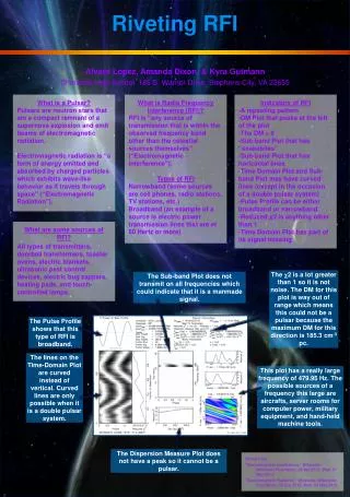
Why is RFI bad? • Because it is vastly more powerful than the astronomical signals we seek. And there’s a lot of it! • Discriminate between `direct’ and `indirect’ effects: • Direct: RFI occurs at the frequency of interest. • Directly interferes with the imaging/sensitivity goals. • Must be able to remove/cancel the unwanted signal. • Indirect: RFI occurs within the band, but not at the frequencies of interest. • RFI power can cause saturation (non-linear response) in signal chain, lowering sensitivity and image fidelity across the full band. • Must design signal chain with very high linearity. • Must be prepared to blank when signals exceed linear region. EVLA Advisory Committee Meeting September 8-9, 2003
Observed RFI Powers and Characteristics • The EMS (Environmental Monitoring System) has been operating for many years at the VLA site. • Have used omnidirectional antennas, or low-gain rotating horns, to monitor the spectrum from 200 MHz to 18 GHz. • A very wide range of strengths and behaviors found. • Situation is worst in L and then S bands, where PFDs above 10-7 watt/m2 are found. • Strongest signals are always intermittent or pulsed. • Examples drawn from L-band are shown in the accompanying table. EVLA Advisory Committee Meeting September 8-9, 2003
L-band RFI L-band (1 – 2 GHz) has a wide range of signal types. The table shows the range of powers, as seen through isotropic sidelobes, for a single emitter. Multiple emitters are normal. The SPFD is the apparent flux density through 0 dBi sidelobes. Multiply by 105 if in main beam. EVLA Advisory Committee Meeting September 8-9, 2003
Linearity • The first line of defense is high linearity. • Table shows the headroom from the nominal operating point to 1% compression. • In addition, we will employ 8-bit sampling at P, L, S bands. • The WIDAR correlator has ~55 dB spectral linearity. NB: 1dB compression point is 13 db above 1% level. EVLA Advisory Committee Meeting September 8-9, 2003
Operating Points and Compression • The plot shows a standard amplifier model, for the EVLA L-band system. • The desired operating point is at (0,0) – defined as the input/output powers for kTDn input noise power. • The red and green lines show the power in 2nd and 3rd harmonics. EVLA Advisory Committee Meeting September 8-9, 2003
Minimizing Harmonics • Non-linear responses shift power from the fundamental frequency to higher harmonics. This is bad, as: • Spectral lines appear where they don’t belong • Continuum power is shifted around the band, lowering sensitivity. • Probable `closure’ errors, limiting imaging fidelity. • We are designing for maximum `headroom’, to minimize harmonic distortions and imaging errors. • Goal is to get 1% compression point >20 dB above nominal input power level kTDn. • We are uncertain of the imaging effects of operating at high levels, near the 1% and 1 dB compression points. • An experiment is being planned to measure this. EVLA Advisory Committee Meeting September 8-9, 2003
Noise Addition at Nominal Operating Point EVLA Advisory Committee Meeting September 8-9, 2003
Noise at nominal operating point plus 2 CW signals +20 dB above nominal EVLA Advisory Committee Meeting September 8-9, 2003
DMEs – the worst case? • DME emission is a good ‘worst case’: not only strong, but highly pulsed: EVLA Advisory Committee Meeting September 8-9, 2003
Examples of L-Band RFI 24-hour plots of the `peak-hold’ spectra at L-band. The LHS shows the entire 1 – 2 GHz band. The RHS shows the DME portion. Greyscale is black at SPFD = -140 dBW/m2/Hz. White coresponds to –170 dBW/m2/Hz Spectral resolution is 100 kHz. EVLA Advisory Committee Meeting September 8-9, 2003
DMEs and the EVLA • These signals will certainly limit L-band performance! • But how badly? We are reasonably confident we can survive emissions from aircraft >100 km distant. • But an airplane within 10 km will probably saturate the signal chain, when the (short) pulses are on. • Must then blank the pulse: • Detect when highest (8th) bit is on at digitizer • Notify correlator that this frame of data is invalid • Blank all products using that frame • Make adjustments to correlation coefficient. • This system will be in place at L and S bands. EVLA Advisory Committee Meeting September 8-9, 2003
Avoiding RFI • As the EVLA will be designed to bring the full bandwidth back to correlator, we will not in general be tuning the LOs to avoid strong RFI. • Strong, common RFI (e.g. DMEs) could be blocked by front-end filters if necessary. • The WIDAR correlator is designed to allow tuning sub-bands to avoid strong RFI. • Sub-band FIR filter designed with 60 dB isolation. • Antenna-based LO offset eliminates aliasing of RFI between sub-bands (only effective with every other sub-band). EVLA Advisory Committee Meeting September 8-9, 2003
Internal RFI Control • External RFI will be a major problem. • We don’t want to exacerbate this with internally-generated RFI emissions. • The EVLA has considerable digital electronics in the antenna – a natural source of emission. • VLA IPG (Interference Protection Group) headed by dedicated engineer. • Must first establish acceptable limits to emission from our digital electronics. • Internal emissions above the acceptable level must be effectively shielded. EVLA Advisory Committee Meeting September 8-9, 2003
Acceptable Limits • The `acceptable RFI’ limits are based on a power flux level being less than 1/10 of the noise power fluctuation from the antenna detector. This leads to a condition: where Gr is the gain of the antenna (w.r.t isotropic) in the direction of the RFI. • Note that the forward gain of the antenna is not a factor in this susceptibility. • This leads to a very stringent standard, as interferometric phase winding will give us considerable help. watt/m2 EVLA Advisory Committee Meeting September 8-9, 2003
Limits for 1 km/sec For the EVLA, with 1 km/sec resolution, and 9-hour integration: EVLA Advisory Committee Meeting September 8-9, 2003
RFI Suppression Progress • To keep internal RFI below these established standards, we must: • Design for low emissions (lower power, slower transitions) • Provide shielding at the module/rack/room levels to keep radiation low. • Utilize RF absorbing material to lower RFI power density. • Tests show shielding better than 110 dB – we expect this will be sufficient to meet ITU standards. EVLA Advisory Committee Meeting September 8-9, 2003
ITU Calculated Maximum Power Flux Density • VLA antenna • 18 m Distance • 10% reflection off sub-reflector EVLA Advisory Committee Meeting September 8-9, 2003
Measured Harmful EIRP from Vertex Room EVLA Advisory Committee Meeting September 8-9, 2003
Sampler Box & H-RackShielding EVLA Advisory Committee Meeting September 8-9, 2003
Estimated Effect of Shielding EVLA Advisory Committee Meeting September 8-9, 2003
Circuit Comparison EVLA Advisory Committee Meeting September 8-9, 2003
Direct Effects of RFI • An interferometer has an inherent advantage over a ‘total power’ single dish: • Interfering signals have a phase and phase rate. • Over time, coherent averaging reduces signal strength – provides 15 to >60 dB isolation. From Memo #49: • Phase and phase rate also be used to identify and remove unwanted emission. EVLA Advisory Committee Meeting September 8-9, 2003
EVLA Advisory Committee Meeting September 8-9, 2003
Example: GPS signals • Each GPS satellite has (on-axis) SPFD of about 106 Jy. • If a satellite traverses a 0 dBi sidelobe, we obtain about 50 dB attenuation: Apparent SPFD is now 10 Jy. • In traversing the entire sky (about an hour?), fringe winding will give about 30 dB further attenuation in D-configuration. Much more in larger configurations. Apparent SPFD is now about 10 mJy (comparable to noise in 1 km/sec channel width) • If in continuum mode, the 1 MHz BW of the GPS signal is diluted by a further 30 dB (in the 1 GHz FE bandwidth). Signal is now about 10 mJy in effective strength (comparable to noise in full BW). • But GPS is the most benign of all transmissions. EVLA Advisory Committee Meeting September 8-9, 2003
Post-Correlation Excision – Removing what we don’t like • For signals that enter the correlator (and which don’t cause saturation or non-linear behavior), we have an ‘ultimate’ weapon: Post-Correlation Excision. • This technique recognizes that RFI is not essentially different than an unwanted background astronomical source. • RFI ‘closes’ -- even for multipath! (Provided it is sampled quickly enough, and modulation or motion doesn’t shift frequencies around.) • RFI is spatially unresolved, so its antenna-based phase and amplitude characteristics can be `easily’ determined. • One can, in principle, then solve for, and remove, the unwanted signal. EVLA Advisory Committee Meeting September 8-9, 2003
Suggested Procedure • Sample fast! (And preferably with narrow channelwidth). • N.B. This is an expensive combination! • Phase rotate affected data to ‘stop’ fringe-winding of RFI. • Easy if the RFI is stationary (same rate as NCP). • Use ‘CALIB-like’ program to solve for RFI phase and gain for every affected frequency channel. • Better: Solve for source and RFI at same time, allowing different gains for each. • Subtract RFI from each affected channel, using gains. • De-rotate data back to phase center, and integrate to reduce volume. EVLA Advisory Committee Meeting September 8-9, 2003
How Fast, How Big? • For the VLA, with SNR = 100, we find, in milliseconds: • These are very short times, leading to very large databases. • At 100 msec, the total rate > 1 GB/second for 16384 channels. • The red zone lies beyond the WIDAR correlator – but natural fringe winding provides 25 dB attenuation in 1 second! EVLA Advisory Committee Meeting September 8-9, 2003
Progress • This method is similar to AT approach, but does not require a separated pointed antenna. • Other approaches being developed elsewhere appear to be similar. • We have no demonstrated examples yet. (Hard to find somebody to work on this). • Considerable development is required – an interesting problem for a suitable person. EVLA Advisory Committee Meeting September 8-9, 2003
Final Level: Blanking • The strongest signals are generally pulsed. • The 8-bit sampling at L and S bands will have the capability to alert the correlator when a voltage level above a certain threshold is met. • The correlator will then blank all computations using that frame. • An adjustment to the correlation coefficient will be needed. (Thought to be small). • Will extend to 3-bit sampling. EVLA Advisory Committee Meeting September 8-9, 2003