Download
1 / 36
360 likes | 371 Views
The EVLA Correlator. P. Dewdney Herzberg Institute of Astrophysics National Research Council Canada. Outline. Correlator Performance Goals Hardware Progress Software Progress System Progress Prototype Testing Installation Estimates Funding, Budget & Schedule Risk Issues.

E N D
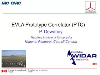
The EVLA Correlator P. DewdneyHerzberg Institute of AstrophysicsNational Research Council Canada
Outline • Correlator Performance Goals • Hardware Progress • Software Progress • System Progress • Prototype Testing • Installation Estimates • Funding, Budget & Schedule • Risk Issues P. Dewdney EVLA Review - May 2006
Key EVLA Processing Capabilities Deep Imaging Polarization • 8 GHz Bandwidth (dual polarization). • Full polarization processing. • Wide-field imaging. • 16,000 channels at max. bandwidth (BW). • >106 channels at narrow BWs. • Spectral resolution to match any linewidth. • Spectral polarization (Zeeman Splitting). Narrow spectral lines Wideband searches • 8 tunable 2 GHz wide bands. • Each band - 16 tunable sub-bands. • Sub-band – independent spectral resolution. • Simultaneous line and continuum. Flexibility Many resources • 1000 pulsar “phase bins”. • “Single-dish” data output to user instruments. • Very fast time sampling (<20 s). High time resolution P. Dewdney EVLA Review - May 2006
Significant Events Since Dec. 2004 • Correlator Chip CDR – Jan/05 • Software Review – Jan/05. • Correlator Preliminary Design Review – July/05. • PCB fabricator contract signed – Jan/06. • Prototype Correlator chip wafers fab’d – Feb/06. • Software Review – Mar/06. • Prototype chip delivery – early Jun/06. • Baseline Board prototype delivery – Jun/06. • Station Board prototype delivery – est. Aug/06.
Hardware Progress • FPGA’s • All FPGA’s are designed, including the Filter Chip. • Station board • Layout is close to completion, including Design-for-Manufacture approval. • Presently undergoing signal integrity simulation. • Prototype fabrication order expected in June. • Baseline Board • Prototype fabrication under way. • Phasing board • Draft specification (RFS) released. • Deferred in time but not reduced in priority. • Other boards • Prototypes for all other boards already fabricated. • Fan-out board needs redesign for better signal margins. • System • Racks designed and prototyped; thermal analysis done. • Power system RFP draft written. • Reliability analysis system in place – first draft of analysis complete. P. Dewdney EVLA Review - May 2006
Station Board Layout • “Daughter” Board - brown. • Power Supplies – pink. • FPGA’s – Green • Connectors – light brown and white. • ~5000 parts. • 140 required for EVLA. Size: ~510 x ~410 mm
Baseline Board Layout • Green chips – front side. • Blue chips – back side. • 8 x 8 array of correlator chips. • LTA chips on the back side. • Recirculation Controller. • ~12000 parts • ~177 required for EVLA.
Software Progress • GUI-based prototype testing software • Complete enough to be useful already. • All FPGA’s covered except Phasing Board. • Provides “engineer’s view of correlator system. • Permanent maintenance value. • Top-level GUI’s now under development. • Virtual Correlator Interface • Well defined except for correlator output area. • Communications protocol well defined except for transport layer. • Master Correlator Control Computer (MCCC) • Work deferred for GUI development. • Architecture/scope well defined. • Real-time control software • “CMIB” processor on each board. • Operating system has been working for a long time. • XML-based communication with “outside world”. • Drivers for FPGA’s are well under way. P. Dewdney EVLA Review - May 2006
Correlator Software People • Sonja Vrcic (Penticton) • Coordinates overall design and specification. • Virtual Correlator Interface (VCI) definition. • Master Correlator Control Computer (MCCC) S/W. • Bruce Rowen (Socorro) • Correlator hardware control S/W (CMIB). • Kevin Ryan (Socorro) • GUI development and hardware control S/W. • Martin Pokorny (Socorro) • Correlator Backend software. • Michael Rupen, John Romney, Bryan Butler, Ken Sowinski, Barry Clark, Bill Sahr (Socorro) • Advisory capacity. P. Dewdney EVLA Review - May 2006
System Progress • NRAO work on correlator room is progressing rapidly. • Design of overall room layout is complete. • Environmental specificationshave been developed. • Air flow & temperature: ~1700 cfm per rack, 15 oC. • ElectroStatic Discharge (ESD) • 90 nm devices used extensively (<1/1000 thickness of human hair) • Humidity specs. • Strict handling and servicing procedures. • Air quality • ISO 14644-1 class 8 + MERV 13 filter. • Racks • “Thermal prototypes” have been built and tested. • “Mechanical prototypes” ditto. • Preliminary fabrication plan is being developed. • Preliminary installation plan is being developed. • Power plant specifications/RFP draft written for acquisition this fiscal year (ends Mar 31/07).
Correlator Testing • Production correlator chip tests • Functional acceptance test by supplier using DRAO-supplied equipment. • At speed, but not over temperature range. • DRAO lab tests: special jig to be fabricated. • HALT/HASS tests being investigated (advanced version of “burn-in”). • Unit PCB hardware tests during production: • Fast functional tests performed at factory in DRAO-supplied equipment. • Unit hardware tests after acceptance • HALT/HASS tests of circuit boards (or equivalent). • Extended functional tests. P. Dewdney EVLA Review - May 2006
Correlator Testing (cont’d) • System Tests • Prototype Stage • Extended testing/debug cycle in lab – all functions. • Many self-tests, simulated observations. • Should confer a high degree of reliability for On-the-Sky tests. • On-the-sky Tests • Final demonstration of prototype tests – designed to be quasi-independent of EVLA S/W. • Begin System Integration with EVLA software (continuing process). • Hardware left at VLA site. • Software Tests after On-the-Sky correlator delivered. • Continued testing with hardware that will remain at the VLA. • Understand interference (RFI) and the “clues” that the WIDAR system provides. P. Dewdney EVLA Review - May 2006
Installation Procedure(Note: Dates from Apr/06 Long Term Schedule) • 06-07: Install –48V DC power system. • 06-07: Install underfloor cables. • 08: Manufacture racks in Penticton. • 08: Install overhead power distribution. • 08: Install control computers, Ethernet switches, backend computers and other COTS equipment. • 08-09: Install boards into racks in an order that maximizes scientific benefit. P. Dewdney EVLA Review - May 2006
EVLA Correlator Group DRAO-based. NRAO-based.
Funding in Canada – No Change Aug/03 – Canadian Treasury Board approval of submitted budget ($C 20M over 5 years). • Most spending in $US. • But see risk factors. P. Dewdney EVLA Review - May 2006
Correlator Summary Schedule Very Uncertain Time Scale
Project Management • Schedule • Detailed schedule periodically updated. • Near-term (target) schedule updated weekly. • Long-term schedule discussed monthly, and cross-checked against detailed schedule. • Budget • Projections updated with schedule. • Bills of Materials (BOM’s) • 1000’s of components. • Maintenance required. P. Dewdney EVLA Review - May 2006
Correlator Documentation • Master Document Tracking Spreadsheet Maintained at DRAO. • 115 documents written so far, including “Memos”. • Additional 23 documents with designations and titles are anticipated. P. Dewdney EVLA Review - May 2006
Principal Design Reviews • Three Design Reviews: • Conceptual (CoDR – Nov, 2001) • Review architecture and overall design. • Preliminary (PDR – July, 2005) • Review detailed designs before prototypes. • Critical (CDR) • Review system before “limited production” stage. • Scheduled for Q2/Q3, 2007. P. Dewdney EVLA Review - May 2006
Non-Technical Program Risks • Funding • Original allotment of funds was over five years. • NRC management was made aware in Aug/03 that this does not fit the project spending profile – they decided that internal cash management could deal with the problem. • Will have to apply for an extension, which in the present climate presents a risk. • Worst case is that project could hypothetically be halted in April 2008. • Active cash management at HIA, NRC level. • Schedule slippage? • Due to a slow start (already happened at the beginning). • Concerns over procurement processes. • This risk is retired. Major procurement contracts are in place except for power supply. • Technical progress slower than the deliberately aggressive initial schedule. • “Re-spins” will present additional schedule risk. • Inadequate contingency? • The contingency fractions are much smaller than most high-tech projects. • Cost risk will be reduced quickly once prototypes are tested. • Exchange-rate changes have been favourable to date. • Inflation not being recognized in funding profile? • Inflation is a corrosive influence. P. Dewdney EVLA Review - May 2006
Technical Program Risks • Technical risk is currently at a maximum • Much design effort and prototype expenditure has taken place. • Prototype hardware is being fabricated (or about to be fab’d), but not received/tested. • But … • Considerable design effort expended to reduce technical risk. • Finely divided testing schemes for circuit boards – every path can be checked independently. • Correlator chip underwent an independent test and verification process, including a major simulation campaign after the “place-and-route” stage. • A separate Design for Manufacturability (DFM) analysis done for circuit boards – results in a major reduction in risk. • Formal system reliability analysis has been done, and will be updated. • Funds and design effort has been expended to minimize technical risk. • We are optimistic and confident that technical risk is reasonably low. P. Dewdney EVLA Review - May 2006
Descoping • The correlator is difficult to split, once designed, and saving is inefficient. • Have not reconsidered descoping options since the budget is currently “under control”. • If the previously-mentioned non-technical risks become imminent concerns, then de-scoping options will have to be revisited. P. Dewdney EVLA Review - May 2006
Project Summary • Are we meeting the required schedule? • We are sticking with the original delivery date, although there is now some squeezing of activities towards the end. • Are we over budget at this stage? • Budget is slimly allocated, but we are not over budget. • Are we planning to deliver on what we said we would do? • Yes, with minor improvements. • What are the major risks at this stage? • Hypothetical funding difficulty in 2008. • Technical risks should be reduced this year as prototypes are tested. P. Dewdney EVLA Review - May 2006