Download

1 / 53
810 likes | 1.32k Views
Chapter 5 Light Wood Frame Construction. Light Wood Framing. Advantages Flexible Easily constructed Economical Disadvantages Burns rapidly, Decays if exposed to moisture Changes volume with moisture changes Framing unattractive (must be covered). History - Prior to mid-1800s.

E N D
Chapter 5 Light Wood Frame Construction
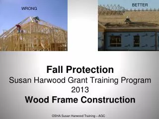
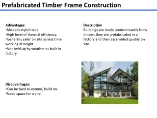
Light Wood Framing Advantages • Flexible • Easily constructed • Economical Disadvantages • Burns rapidly, • Decays if exposed to moisture • Changes volume with moisture changes • Framing unattractive (must be covered)
History - Prior to mid-1800s • Timber Frame timber with masonry timber with earth fill • Interior walls were simple plank structure • Trees were plentiful, and labor was intense. • Craftsmen were available, but tools were limited – and had to be operated by hand.
History - mid 1800s • Light wood framing advanced by • Development of water powered saw mills • Machine made nails became available • Earliest Version of Lt. Wood Framing • Balloon Framing Long lengths of material was plentiful Wood members were small & easily handled Provided for lateral stability
Balloon Framing • Erection of wall framing members on a wood sill secured to the foundation and lapped against the floor joists. • Second floor joists lapped into the wall framing system. • Roof framing then set on top of wall plates. Roof rafters tied to ceiling joists secured lateral displacement of exterior walls. • Components were light in comparison to timber structures, and erection required minimal labor than before. The practice was a more efficient use of material.
DISADVANTAGES OF BALOON FRAMING • Long, straight lengths of material diminished in availability as more structures were built. • When buildings caught fire, the wall cavity of balloon framing allowed fire & smoke to chimney all the way to the roof, and structures burned rapidly. • Since the wall and floor structure were built integrally, most of the framing work was done off the ground, where level conditions might not exist.
PLATFORM FRAMING • With the disadvantages of balloon framing, the platform frame system evolved. • The floor structure was first built onto the foundation sill, then decked to provide a ‘platform’ on which to work. • Ground-floor walls were erected with a top plate to receive the second floor joists, which became a sill on which to erect the upper floor joists – which, when decked became another platform. • Single floor framing was more plentiful because of shorter lengths.
Building Sequence • Architect Plans and Designs the Facility – Then Prepares Design and Construction Documents • Involve a selected Contractor, who: • Obtains Building Permit • Purchases necessary materials • Selects Sub-Contractors for each phase of work • Excavation for utilities, foundations • Install Underground utility lines (electrical, plumbing) • Foundation construction • Floor Construction • Erect Framing for Structure
Excavate & Place Foundations • Materials Typically Used: • Site Cast Concrete • Concrete Masonry Units • Reinforcing Steel • Tie wire • Anchor Bolts • Foundation and Basement Wall Construction • Construction for support of loads • Damp proofing and/or perimeter insulation
Foundation Wall Systems Sill Anchor Concrete or CMU Wall Damp-proofing Drainage Stone under floor slab with Vapor Barrier Gravel for Drainage Perforated Drainage Pipe Concrete grade beam
Installation of Plumbing Drainage Piping Underground Plumbing
Example of grade beam monolithic with concrete floor Wall Load Granular Base Thickened Slab on grade
Installation of plastic vapor barrier under concrete floor Vapor Barrier Granular SubBase
Foundation Insulation • Some building codes require perimeter insulation at foundations – especially in cold climates. • Insulate the Crawl Space or Basement Walls • Attach to Platform or on Ground • Vapor Barrier
Building the Platform Frame in Wood Floor With Crawl Space • Sequence of Assembly • Install sills with insect barriers • Bolt sill members to the Foundation • Install floor framing and bridging • Install floor decking
Attachment to the Foundation • Sill Material • Treated for resistance to insects & decay in damp climates. • Install insect shields • Sill Attachment with anchor bolts
Floor Framing Options FRAME WITH DIMENSION LUMBER FRAME FLOORS USING TRUSSES
Floor Framing Spacing & Splicing • Spacing • Factors that determine joist spacing: • Floor Loading & Span Length • Strength of Joist Material Used • Type & thickness of floor decking • Designation - Inches “o.c.” (on center) • Typical - 12” , 16”, or 24” – to fit standard lumber lengths)
Decking over Floor Framing • Materials Used • Plywood or OSB • Concrete or gypsum is poured over second floor decks for sound deadening • Installation • Deck is laid perpendicular to floor joists • End joints are staggered to brace joists • Power nails, screws, construction adhesive
Building Sequence for Ground Floor Walls Layout • Sole plates installed to define wall locations • Wall Framing - Lay out studs & assemble with single top wall plate • Tilt up walls on the Platform & fasten to sole plate • Install second layer of top wall plate to tie all partitions and walls together. • Install Wall Sheathing • Corner bracing required for lateral stability – usually OSB or plywood at all exterior corners
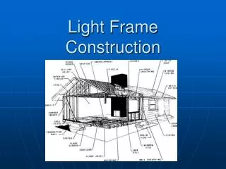
Framing Terminology Top Plate - Doubled Stud Header Sheathing Decking Sole Plate
Headers • Headers are beams installed over openings to carry weight of second floor or roof loads. • Sizing Factors: Load, Span, Material • Materials: dimension lumber, Laminated wood, orSteel
Erecting the Wall Framing • Build framing on the Platform & Tilt-up, brace, and fasten to sole plates.
Double Top Plate • Joist Support • Tie Framing Together
Double Top Plate Double Header Header Supports
Wall Sheathing • Materials: • OSB or Plywood for corner bracing • Insulating Sheathing - (no structural qualities)
Exterior Wall Sheathing: • Joins & stabilizes the structure • Resists uplift • Resists racking & lateral forces • Provides surface for finish material
Building Sequence PLATFORM & 2ND Story Walls • Erect 2nd Story Platform • Similar to 1st Floor Sequence • Install 2nd Floor access (stairs) • Erect 2nd Story Walls & Sheathing • Similar to 1st Floor Sequence
Building Sequence Attic Floor & Roof • Options • Build-in-place ceiling joists, rafters, and bracing, OR • Prefabricated Trusses, OR • Combination
Roof Framing Built-in-Place Ridge Board Rafters
LOOKOUTS TO FORM OVERHANGS GABLE FRAMING
Note Strand Orientation Hurricane Clip