Download
1 / 27
280 likes | 487 Views
Overview of LCLS-II Cryomodule Plans. E. Daly for LCLS-II Cryomodule Collaboration AWLC Meeting 14 May 2014. Acknowledgements. Special Thanks – T. Peterson, T. Arkan , A. McEwen, G. Neil JLab, FNAL and SLAC colleagues XFEL Project Team at DESY & CEA/ Saclay. Outline.

E N D
Overview of LCLS-II Cryomodule Plans E. Daly for LCLS-II Cryomodule Collaboration AWLC Meeting 14 May 2014
Acknowledgements Special Thanks – T. Peterson, T. Arkan, A. McEwen, G. Neil JLab, FNAL and SLAC colleagues XFEL Project Team at DESY & CEA/Saclay E. Daly, AWLC, 14MAY2014
Outline Overview of LCLS-II Collaboration Design Highlights Prototypes Production Strategy CM Production Preparations Summary E. Daly, AWLC, 14MAY2014
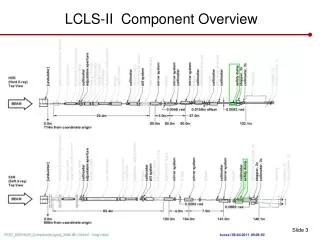
LCLS-II Project Collaboration • 50% of cryomodules: 1.3 GHz • Cryomodules: 3.9 GHz • Cryomodule engineering/design • Helium distribution • 50% of cryomodules: 1.3 GHz • Cryoplant selection/design • Processing for high-Q • LLRF design • Undulators • e- gun & associated injector systems • Undulator Vacuum Chamber • Also supports FNAL w/ SCRF cleaning facility • Undulator R&D: vertical polarization • R&D planning, prototype support • processing for high-Q • e- gun option E. Daly, AWLC, 14MAY2014
Cryomodules for LCLS-II (CDR) Courtesy of T. Peterson, SRF Weekly Mtg, DEC 2013 E. Daly, AWLC, 14MAY2014
Cryomodule Collaboration Courtesy of T. Peterson, SRF Weekly Mtg, DEC 2013 • Fermilab is leading the cryomodule design effort • Extensive experience with TESLA-style CM design and assembly • Basis is 3-D model & drawings of similar Type-IV CM • Jefferson Lab and Cornell are partners in design review, costing, and production • Cornell and JLab both have valuable CW CM design experience • Jefferson Lab sharing half the 1.3 GHz production • Recent 12 GeV Upgrade production experience • Argonne Lab is also participating in cryostat design • Beginning with system flow analyses and pipe size verification • Experienced SRF and cryogenic personnel at ANL may be available for other collaborative tasks E. Daly, AWLC, 14MAY2014
1.3 GHz CM Modifications for LCLS-II Courtesy of T. Peterson, SRF Weekly Mtg, DEC 2013 • Design Specification – Qo> 2.7 x 10 10 @ 16 MV/m, < 100 W per CM at 2K • High Qo Team has intense focus (see A. Grasselino’s AWLC May 2014 talk) • Design Points - TESLA Type 3+, XFEL, and Type 4 CM designs • Modifications for CW heat loads • Larger chimney pipe from helium vessel to 2-phase pipe • Larger 2-phase pipe (4 inch OD) • Closed-ended 2-phase pipe • Separate 2 K liquid levels in each cryomodule • 2 K JT valve on each cryomodule • End lever tuner and helium vessel design for minimal df/dP • Details in Y. Pischalnikov’s AWLC May 2014 talk • Double-layer inner magnetic shield • SC Magnet – splits in half for installation outside cleanroom • Two cool-down ports in each helium vessel for uniform cool-down of bimetal joints • No 5 K thermal shield • But retain 5 K intercepts on input coupler • Input coupler for ~10 kW CW • Details in N. Solyak’s AWLC May 2014 talk E. Daly, AWLC, 14MAY2014
LCLS-II CM Schematic Note : Slope of 2-phase helium in pipe due to tunnel slope (6 cm over 13 m), need single connection to 300 mm pipe Courtesy of T. Peterson E. Daly, AWLC, 14MAY2014
Prototype 1.3 GHz CM Description Courtesy of T. Peterson, SRF Weekly Mtg, DEC 2013 • Each lab produces a prototype CM • Main Objectives for Prototypes • Establish working collaboration for production with Jlab – each lab produces a prototype cryomodule, then provides production cryomodules • Demonstrate CW operation of 8 high-Q cavities in a cryomodule • Prototype cryomodule planned for use in LCLS-II • New cryostat design and procurement with Type 3+ spacing • Use existing cavities in prototype CMs • Incorporate High-Q0 surface process development in a logical way • Peripherals • New He vessel • Slight modifications to HOM coupler • End-lever tuner • RF power couplers, modify TTF couplers or procure new ones (more later) • Do these developments once – the primary cryomodule design effort E. Daly, AWLC, 14MAY2014
LCLS-II Prototype Cryomodule Courtesy of T. Peterson, SRF Weekly Mtg, DEC 2013 8 cavities (End Tuner) + 1 “Splittable” SC Quad, 6 Current Leads ~50A -JT Valve -Splittable Quad -BPM -Gate Valve E. Daly, AWLC, 14MAY2014
Strategy – One Design, Two Production Lines Designs for Prototype and Production CMs (aim to satisfy PR and CM FRS) • Identical Prototypes - utilize as much existing hardware as possible to reduce schedule risk and reduce overall costwhile achieving the same performance as the production CMs • Identical Production Designs - utilize as much of the DESY/XFEL design as practically possible to reduce schedule risk and reduce overall cost • FNAL produces 16 CMs; JLab produces 17 CMs Identical Parts Received at Partner Labs • Well-developed drawing packages, clear requirements and specifications • Concurrent reviews within LCLS-II project • Procurement activities – lead technical contacts at Jlab/FNAL/SLAC work together during all phases Identical Tooling Interfaces • Interfaces between CM hardware and tooling are identical • Avoid adding custom features to CM • Adapt non-CM hardware interfaces to Lab-specific tooling Equivalent Processes yielding Equivalent Performance • Recognize that some tools are different at each lab (e.g. HPR, vertical testing systems, vacuum leak checking equipment, etc.) • Monitor key process variables in consistent fashion (e.g. samples to verify etch rates) E. Daly, AWLC, 14MAY2014
Leveraging XFEL’s Existing CM Experience XFEL Production - Four cavities per test stand Tunnel construction is underway Production of CMs is currently ramping up! Start operations in April 2017, see http://www.xfel.eu/project/construction_milestones/ CM ready for testing (can test 3 CMs at once) E. Daly, AWLC, 14MAY2014
Opportunity to Learn from CEA Colleagues Production of CMs is currently ramping up! E. Daly, AWLC, 14MAY2014
Leveraging FNAL’s ILC-style CM Production Development Cavity String Assembly Insertion of Cold Mass into Cryostat Assembly Cryomodule Ready for Transport On-site Cold Mass Assembly Courtesy of T. Arkan, FNAL E. Daly, AWLC, 14MAY2014
LCLS-II Cavity/CryomoduleProcess at JLab JLAB SRF Facility Supplier Partners • Receiving in SRF Inventory • Mechanical Inspection CMM Courtesy of A. McEwen, JLab • Cavity /Helium Vessel Prep. & Test • VTA RF Test in liquid Helium @ 2 K Cavity String Assembly & Leak Test • Assemble Cavity String -Class 100 Clean Room Courtesy Chi-Chang Kao, SLAC Cryomodule Assembly • Instrumentation & Wiring • Tuners, MLI– Multi Layer Insulation, • Cryogenic Circuits , magnetic shielding, alignment • Super Insulation Cabling & Shield • Vacuum Vessel & Final Alignment • Install Cryogenic Supply Interfaces • Horizontal Test Preparation • Pressure Test & Leak Check (vacuum) Commissioning at SLAC Install Cryomodules in Accelerator, cool to 2 K • Weld & certify leak tight , pressure test • check Controls, • Gradient & Dynamic Heat Load - Qo Cryomodule Test in “Test Cave” • Cryomodule integrity @ 2 K • Tuners - Range, Hysteresis, & Resolution/ Sensitivity • Cavities for Gradient & Dynamic Heat Load Qo LCLS-II 1.3 GHz Cryomodule LCLS-II 1.3 GHz Dressed Cavity, Doped and Ready for VTA Testing Cryomodule shipping to SLAC • JLAB support for installation of first 3 Cryomodule E. Daly, AWLC, 14MAY2014
SRF Facilities at JLab Start Ship E. Daly, AWLC, 14MAY2014
CM Production Preparations Adapt existing infrastructure and facilities to accommodate LCLS-II components, sub-assemblies, final assembly and testing Define processes required for component handling, assembly and testing Develop test plans – key activities are cavity qualification from vendors and cryomodule acceptance testing Employ SRF QA Tools used for 12 GeV 100 MV CW cryomodules (aka C100) production and SNS production E. Daly, AWLC, 14MAY2014
Infrastructure, Tooling & Facilities (JLab) • Vertical Testing of Bare/Dressed Cavities • Planned rate - 4 cavities per week • Cavity String, Cold Mass and CM Assembly Tools • Planned rate – 1 CM per month • Horizontal Testing Bench – supports Qo R&D and production efforts • Planned rate ~ 1 cavity per CM • Cryomodule Testing Facility (CMTF) • Planned rate – 1 CM per ~ 6 weeks E. Daly, AWLC, 14MAY2014
Cavity String Assembly in Clean Room (JLab) “Lollipop” supports for each cavity TBD for SC magnet and bpm Use mobile rail system rather than rail-in-floor used at DESY, CEA/Saclay and FNAL Transfer to CM assembly rails for cold mass assembly E. Daly, AWLC, 14MAY2014
JLab CMTF : Production “Bottleneck” • HPRF system suitable for individual cavity testing or 8 cavities in short duration steady state • TBD system for testing SC magnet • Magnetic shielding encloses testing volume reducing external fields to ~50 mG • Cryogenic capacity for testing individual cavities in CW mode • End Caps – specific for LCLS-II CM testing • Interface to CM piping and existing junction box using u-tubes E. Daly, AWLC, 14MAY2014
Facilities Improvements : Testing in CMTF • End Cans • Connects CM to CTF valve box via u-tubes • Interfaces for valves, LL and diodes to monitor and control helium flow/inventory • Provides reliefs for primary circuit, shield circuit and insulating vacuum space • HPRF • Procure 1.3 GHz 10 kW Solid-State Amplifiers (SSAs) & Circulators • Modify Waveguide and Interlocks • Run line power to SSA/Circulators • Provide controls in CMTF Control Room • LLRF • RF Instrumentation (arc detectors, IR sensors, etc.) • Provide controls in CMTF Control Room • Software development • Cryogenic Test Facility (CTF) • Increase return side piping to reduce overall pressure drop from CMTF • Improve recovery system (pumping, compression) to provide base pressure of 0.031 atm (23 torr) in the CM helium bath E. Daly, AWLC, 14MAY2014
Summary • Goal for production of CMs at Jlab/FNAL is “identical design, identical parts, equivalent processes to yield equivalent performance” • Infrastructure development supports this goal • Overall Plan for Cryomodule Design & Production • R&D / Design Modifications Complete FY14 • Infrastructure / Tooling FY14/15 • Prototype CMs (2 units) FY15 • Start of Production 1.3 GHz CMs (33 units) FY16 • Rates of 1 CM per 6 – 8 weeks in current plans • Start of Installation at SLAC FY17 E. Daly, AWLC, 14MAY2014
Back Up Slides E. Daly, AWLC, 14MAY2014
Facilities Improvements: Assembly Tools (JLab) *Design exists, purchase copies • Main Cavity Tools • Clean room tooling - small fixtures for coupler installation, flange alignment, VTA testing hardware* • Cavity Handling Cages* • Cavity Processing Tool Improvements (e.g. HPR, Heat Treatment Furnace, Horizontal EP) • Two sets of carriages for cavity string • Main Cold Mass and Cryomodule Assembly Tools • Cold Mass Spreader Bar - Supports / Positions Cold Mass for cavity string attachment* • Cold Mass Installation into Vacuum Tank • Vacuum Tank Supports • Spreader Bar - Lifts Cryomodule* • Shipping Frame & End Caps* E. Daly, AWLC, 14MAY2014
Vertical Test Area / Horizontal Test Bench (JLab) VTA Up to four test stands available for production acceptance testing capable of testing one cavity at a time Utilize same cavity hardware (test flanges, feedthroughs, etc.) provided by project to cavity suppliers Small modifications required to existing supports Ensure low magnetic field environment (“magnetic hygiene”) HTB Support High Qo R&D Plan to conduct five tests during production effort to provide feedback on cavity assembly process or for production development activities Modifications to top hat for XFEL-style FPC and small modifications to existing supports E. Daly, AWLC, 14MAY2014
Cold Mass / VV Assembly “Lollipop” supports for each cavity TBD for SC magnet and bpm Use two-rail system to transfer cavity string onto Return Pipe Use two-rail system to transfer cold mass into vacuum vessel Crane access in high-bay for shipping E. Daly, AWLC, 14MAY2014
CMTF Conceptual Layout JUNCTION BOX BAYONET BOX END CAP BAYONET U-TUBE CAVE DOOR (CLOSED) HEAT EXCHANGER End view of CM with bayonets connecting JB, HX and BB E. Daly, AWLC, 14MAY2014