Download
1 / 20
200 likes | 312 Views
C.Y. Tan for Proton S ource group PIP II Collaboration Meeting 03 June 2014. Overview of Booster PIP II upgrades and plans. PIP II Booster parameters.

E N D
C.Y. Tan for Proton Source group PIP II Collaboration Meeting 03 June 2014 Overview of Booster PIP II upgrades and plans
PIP II Booster parameters 50% higher flux than the planned PIP operations which is expected to double present flux level. (4.3e12 protons @15 Hz at the end of PIP I) 30% decrease in space charge tune shift @ 800 MeV. Longitudinal emittance determined by Recycler slip stacking requirements. PIP II Collaboration Meeting, June 2014; C.Y. Tan
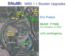
New injection point into Booster New injection point at L11. Old injection point at L1 PIP II Collaboration Meeting, June 2014; C.Y. Tan
Overview of required R&D • New injection point at L11. • New injection girder. • Space charge mitigation: painting. • New stripping foil. • H0 , H- absorber • RF capture • capture scheme: paraphasing or direct injection into buckets • 2nd harmonic cavities (considered but probably unnecessary). • Transition crossing • RF focusing method. • RF focus free method (flattening of RF amplitude) • 2nd or 3rd harmonic cavities. (can also be used in RF focusing method) • γt jump system • requires resurrection/rebuild of old system. PIP II Collaboration Meeting, June 2014; C.Y. Tan
Overview (cont’d) Damper upgrades and collimation system • longitudinal quadrupole damping when going through transition. • Will require voltage overhead in RF system • longitudinal coupled bunch mode damping at high field. • Will require an increase in RF power • Transversedampers for coupled bunch modes. • Higher intensity may require more power for kickers. • Evaluation of present collimation system w.r.t. expected PIP II loss Beam quality at extraction • emittances determined by Recycler admittances. • 18 π mm mrad (6 σ normalized) • 0.08 eV s (97%) PIP II Collaboration Meeting, June 2014; C.Y. Tan
New injection girder Beam can enter either horizontally or vertically. A new 3 bump system that can take 800 MeV beam (2x stronger) Beam painting to mitigate space charge effects because of longer injection time (0.6 ms) Carbon foil for stripping (15 turns vs 315 turns) • Lifetime effects. New beam absorber for H0 and H- • Build inside a gradient magnet. • Design new stronger and shorter gradient magnets to make space for an absorber. (Preferred) PIP II Collaboration Meeting, June 2014; C.Y. Tan
Foil For a std. foil thickness 380 mg/cm2 (1.15 mm) 400 MeV -> 99.9% efficiency to protons 800 MeV -> 99.1% efficiency to protons To match 400 MeV efficiency at 800 MeV foil thickness needs to increase to ~545 mg/cm2 current foil holder current foil At 800 MeV with 7E12 injected at 15 Hz Injection power increases to ~ 13 kW. For a 2% loss -> 260 Watts on downstream gradient magnet. -> Need to provide injection absorber PIP II Collaboration Meeting, June 2014; C.Y. Tan
Stripping efficiencies at 800 MeV Field in 4th chicane Strip immediately stable PIP II Collaboration Meeting, June 2014; C.Y. Tan
Vertical Injection Concept sep foil 1 2 3 4 ORB 1-2: 22 mr ORB 3-4: 33 mr DC sep: 78 mr H- H- H0 aperture PIP II Collaboration Meeting, June 2014; C.Y. Tan
Injection painting for space charge mitigation Green: injected beam. Red: phase space after painting. Beam line matching conditions for two painting scenarios. Left paint in both planes in the ring (SNS) and right paint horizontal in ring and steer (angle mismatch) from beam line (JPARC). Note: ellipses were calculated for 1GeV injection. PIP II Collaboration Meeting, June 2014; C.Y. Tan
Capture (adiabatic at 800 MeV) 0.6 ms injection time. 0.4 ms adiabatic ramp to full voltage (1 MV) PIP II Collaboration Meeting, June 2014; C.Y. Tan
Capture (bucket to bucket injection) Chopping 180 deg Chopping 120 deg 0.6 ms injection time. Chopping is required to get the correct bunch pattern into the bucket. 2 mA for 0.6 ms gives 7.5e12 particles. May need flattened front porch for injection PIP II Collaboration Meeting, June 2014; C.Y. Tan
Transition crossing Transition crossing at 4.2 GeV More RF for focusing during transition. ~25% more RF implies 3 – 4 more RF cavities using present design. (22 – 23 cavities) Example shown here is the compensation of the effect of space charge that is defocusing before transition & focusing after transition. Increase RF voltage before transition Increase RF voltage again to damp out quadrupole oscillation. PIP II Collaboration Meeting, June 2014; C.Y. Tan
Perpendicular biased cavities Simulations of use at injection for PIP I and possible use as main RF cavity is underway. Units in mm 195 Ferrite 70 200 390 220 40 BeO 490 Designed by G. Romanov Example here: 2nd harmonic cavity PIP II Collaboration Meeting, June 2014; C.Y. Tan
What was done recently L = 5” l/4 = L * √(me) center conductor 1.5” outer conductor AL400 short Work done by D. Wildman and R. Madrak Measured m and Q (tan d) resonantly with a 1.5” OD sample of AL400: measure fres, then with c = f l PIP II Collaboration Meeting, June 2014; C.Y. Tan
Old (S11) and New(Resonant) Measurements Work done by D. Wildman and R. Madrak PIP II Collaboration Meeting, June 2014; C.Y. Tan
Dampers Longitudinal coupled bunch and quadrupole mode dampers • More RF volts is required whatever scheme is chosen. • E.g. Increase the number of RF cavities from 18 to 21 using present design will give ~150 kV. • Change from parallel biased cavities to perpendicular biased cavities could potentially increase volts/cavity from ~50 kV to ~60 kV and give 180 kV increase. • PIP I is working on improving present cavity design and perpendicular cavity design. Transverse and longitudinal dampers • PIP I upgrading analog dampers to digital dampers. PIP II Collaboration Meeting, June 2014; C.Y. Tan
Collimators PIP I plan is to reinvestigate present collimation operations and issues related to PIP I goals. • No upgrade of collimation is presently planned. PIP II Collaboration Meeting, June 2014; C.Y. Tan
Loss requirements Historically Booster losses is maintained <= 525 W ring wide. Independently set beam loss monitor trip points at each long and short straight sections. For PIP II • Keep ring wide activation at the present level would be recommended • Control loss points to be at collimators and beam dump • Notching in Linac will help reduce losses. Presently 3 bunches are kicked out => 95% efficient. • Ability to keep notch clean after multiple turns • Synchronization of Linac and Booster for extraction kickers and notch PIP II Collaboration Meeting, June 2014; C.Y. Tan
Summary There is an R&D effort in place. Preliminary work has been started to find solutions to potential problems that we have identified: • New injection girder • RF capture • Transition • RF cavities Beam quality • Determined by keeping instabilities under control. • Constrained by Recycler requirements. PIP II Collaboration Meeting, June 2014; C.Y. Tan