Download
1 / 21
210 likes | 276 Views
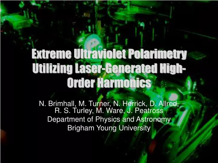
Extreme Ultraviolet Polarimetry Utilizing Laser-Generated High-Order Harmonics. N. Brimhall, M. Turner, N. Herrick, D. Allred, R. S. Turley, M. Ware, J. Peatross Department of Physics and Astronomy Brigham Young University. Overview and Conclusions.

E N D
Extreme Ultraviolet Polarimetry Utilizing Laser-Generated High-Order Harmonics N. Brimhall, M. Turner, N. Herrick, D. Allred, R. S. Turley, M. Ware, J. Peatross Department of Physics and Astronomy Brigham Young University
Overview and Conclusions • We have constructed an extreme ultraviolet (EUV) polarimeter that employs laser-generated high-order harmonics as the light source. • This instrument represents a potential ‘in-house’ instrument at facilities developing EUV thin films. • The source has high flux, a wavelength range from 8-62 nm, and easily rotatable linear polarization. • The instrument has a versatile positioning system and can measure reflectance of multiple wavelengths of light simultaneously. • We have compared reflectance data with that taken at the Advanced Light Source (ALS) and with calculated data. These measurements agree well.
Introduction: Extreme Ultraviolet Optics and Optical Constants • Optical constants in the EUV are typically unknown, incomplete, or inaccurate. • This is important for those designing EUV optics for applications such as astronomy, lithography, or microscopy. Two examples • IMAGE satellite 2000 (above) • ThO2 optical constants (right)
Optical Constants EUV light sample incident angle (Θ) Optical constants are determined by measuring reflectance as a function of angle of a sample at a fixed wavelength and polarization, then fitting this data to the Fresnel equations.
Sources of EUV light • Synchrotron Source • High flux • Wide, continuous wavelength range • Not local, expensive to run, large footprint • Fixed polarization • High Harmonics • Fairly high flux • Wide wavelength range, good spacing of wavelengths throughout the range • Local • Easily rotatable linear polarization • Plasma Source • Low Flux • Wide wavelength range, only a few wavelengths in the range • Local • Unpolarized
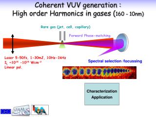
High Harmonic Generation EUV Generation EUV Grating 800 nm, 30 fs, 10 mJ Laser Pulses EUV Light MCP Detector Gas (He, Ne, Ar) • Wavelength range from 8-62 nm • Flux of 6x10⁸ photons/second • Easily rotatable linear polarization • Fairly high flux • Wide wavelength range with good spacing of wavelengths within the range • Easily rotatable linear polarization • Small footprint, low cost of operation • Potential ‘in-house’ instrument at facilities developing EUV thin films λ = 800 nm / q Orders 37 to 77 Wavelengths of 10-22 nm
Instrument Overview EUV generation f=100 cm focusing lens dual rotation stages turbo pumps secondary gas cell gas (He, Ne, Ar) sample 800 nm, 30 fs, 10 mJ laser pulses EUV grating aperture rotatable half-wave plate turbo pump turbo pump MCP CCD • Easily rotatable linear polarization • Ability to measure reflectance of multiple wavelengths simultaneously • Extensive scanning ability
Polarimeter Positioning System • The positioning system is made up of six motors, each controlled by a single computer. • The diffraction grating is placed after the sample, allowing simultaneous reflectance measurements at multiple wavelengths.
Controlled Harmonic Attenuator 90% 90% secondary gas cell 0.01% 0.01% We increase the dynamic range of our detection system with a secondary gas cell that acts as a controlled harmonic attenuator.
Laser Power Discriminator Stability of our high harmonic source is important to the accuracy of polarimetry measurements. • Shot-to-shot variations in the laser pulse energy lead to about 37% variation in harmonic signal. • Averaging 100 shots decreases variation to about 7%. • To further increase repeatability, we implemented a laser energy discriminator, decreasing variations to about 2%. A sample of the incident laser beam is imaged in real time simultaneously with harmonics to provide per-shot energy monitoring
Reflectance Measurements • Sample: • thermally oxidized silicon, 27.4 nm SiO2 layer. • High-harmonic generation parameters: • 100 torr helium gas • Measurement parameters: • all measurements averaged over 100 shots where the variation in the laser power was +/-5% • secondary gas cell pressures ranged in value from 0 to 2.8 torr (attenuation of about 3 orders of magnitude) • dark signal taken simultaneously with measurements • measurements taken on three separate days to examine possible systematics in repeatability.
Conclusions • We have constructed a new instrument that uses high-order harmonics to measure optical properties of materials in the EUV. • Our source has a wide wavelength range, high flux, and easily rotatable linear polarization. • Our instrument has a sophisticated positioning system and is efficient in that simultaneous reflectance measurements can be made at multiple wavelengths. • We have compared reflectance measurements with those taken at the ALS and computed data. These measurements agree.
Future Work • Investigate a new measurement technique • In some regions where reflectance is very low, it may be difficult to measure absolute reflectance accurately (at near-normal angles, absolute reflectance is often on the order of 10-4). • It may, however, be possible to measure a very accurate ratio of p- to s-polarized reflectance. Our instrument has the capability to quickly toggle between polarizations to measure a very accurate ratio. • Variation in the laser source or harmonic generation parameters over time scales longer than minutes will no longer be a concern. Also, dynamic range issues will no longer be a problem. • Measure optical properties of materials in this wavelength range • Optical constants • Bonding effects on optical properties • Oxidation rates • Roughness effects
Thank you We would like to recognize NSF grant PHY-0457316 and Brigham Young University for supporting this project.
Spectral Resolution • Defocusing is the limiting factor, giving a spectral resolution of about 184.
Future Work 1.2 0.8 Rp / Rs 0.4 incident angle (from grazing) k n 0.5 0.8 1.2 1.5