Download

1 / 21
210 likes | 352 Views
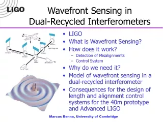
Wavefront Sensing in Dual-Recycled Interferometers. LIGO What is Wavefront Sensing? How does it work? Detection of Misalignments Control System Why do we need it? Model of wavefront sensing in a dual-recycled interferometer

E N D
Wavefront Sensing in Dual-Recycled Interferometers • LIGO • What is Wavefront Sensing? • How does it work? • Detection of Misalignments • Control System • Why do we need it? • Model of wavefront sensing in a dual-recycled interferometer • Consequences for the design of length and alignment control systems for the 40m prototype and Advanced LIGO Marcus Benna, University of Cambridge
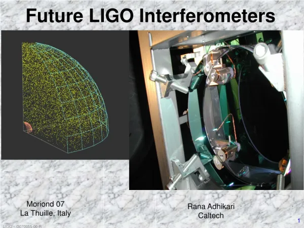
LIGO – Laser Interferometer Gravitational-Wave Observatory • Gravitational Waves are predicted by Einstein’s general theory of relativity • Due to their weak interaction with matter, they have never been observed experimentally • Gravitational waves effect tiny lengths changes between two test masses (strains of the order of h~10-21) • LIGO employs interferometric techniques to measure those strains Marcus Benna, University of Cambridge
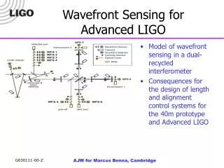
Advanced LIGO Layout- requires numerous control systems • Five length degrees of freedom • Twelve angular degrees of freedom (six for each of pitch and yaw) • Beam splitter serves as reference • Input beam direction needs to be controlled Marcus Benna, University of Cambridge
What is Wavefront Sensing ? • Mirror endowed test masses are suspended from a single loop of wire • Length sensing detects changes in the separation of the mirrors, which can hence be corrected for to keep the light in resonance in the cavity • Alignment sensing (=wavefront sensing) detects angular misalignments of the mirrors in pitch and yaw Marcus Benna, University of Cambridge
Angular degrees of freedom Marcus Benna, University of Cambridge
Hermite-Gaussian Modes • Hermite-Gaussian modes define a complete orthogonal set of functions describing the transverse beam profile • The fundamental TEM00 has a Gaussian profile in both transverse directions • Higher order modes have more complex profiles with a number of zeroes given by the mode indices for the two transverse axes Marcus Benna, University of Cambridge
Hermite-Gaussian Modes II As compared to plane waves, Hermite-Gaussian modes acquire an additional phase shift when passing through their waist, which is the point of minimal beam diameter. This is called a Guoy phase shift. Marcus Benna, University of Cambridge
Guoy Phase Telescope • Adjusts beam diameter to make spot fit onto photodiode • Introduces Guoy-phase advance of our choice Marcus Benna, University of Cambridge
Length Sensing andPound-Drever-Hall Locking • Lengths need to be controlled to within 10-10m • Want a linear, zero-crossing error signal • But cannot measure phase shift of carrier light directly because frequency is much too high (300THz) • Hence we need some trickery… Marcus Benna, University of Cambridge
Length Sensing andPound-Drever-Hall Locking II • Modulate carrier light with a Pockels cell to apply radio-frequency (RF) sidebands before it enters the cavity • Place RF-photodiode at output port and observe radio-frequency beats between carrier and sidebands • Demodulate signal by “mixing” (i.e. multiplying and time-averaging) it with signal from same local oscillator that drives Pockels cell • This gives you a linear, zero-crossing error signal -> active null instrument Marcus Benna, University of Cambridge
Extension to Alignment Sensing • Misaligned optics tilt reflected beams with respect to nominal optical axis of cavity • For small angles (<< far field diffraction angle) this is mathematically equivalent to adding a TEM10 component to the fundamental Gaussian TEM00 mode • Hence we can describe any tilted mirror as a source of TEM10 mode • On a normal photodiode the TEM10 mode wouldn’t show up, because odd functions are averaged to zero • Hence use split photodetector to observe beats between carrier TEM00 and sideband TEM10 for example Marcus Benna, University of Cambridge
Misalignment of a simpleFabry-Perot cavity • Incident laser beam • TEM00 mode resonant in cavity • Input Test Mass • Tilted End Test Mass • Split Photodiode • Reflected light without misalignment • Reflected light is displaced due to misalignment. Transverse intensity profile (solid) with modal decomposition (dashed) Marcus Benna, University of Cambridge
Why do we need alignment sensing ? • As always in LIGO, the answer is: To reduce noise! • Misaligned optics introduce excess noise • Coupling into higher order modes represents effective loss of beam power Marcus Benna, University of Cambridge
Current Design of the Advanced LIGO Control System • Two pairs of resonant sidebands • One resonant in both power recycling and signal recycling cavity, the other one only in power recycling cavity • One pair of sidebands as low as possible in frequency (limited by dimensions of vacuum envelope) the other as high as possible (limited by current demodulation technology) • Three output ports: Bright port, dark port, pick-off Marcus Benna, University of Cambridge
Building a model of alignment sensing in a dual-recycled interferometer • Calculate steady state field of TEM00 mode in perfectly aligned state • Treat any tilted mirror as a source of TEM10 mode • Propagate both modes to the various output ports and perform demodulation • Construct the most favorable wavefront sensing matrix, which relates misalignments in the six different degrees of freedom to signal levels in the six wavefront sensors, by choosing appropriate locations, demodulation frequencies and phases for the sensors • The goal is to make this sensing matrix as diagonal as possible • Implement all this in a Mathematica notebook • Involves numerous approximations… Marcus Benna, University of Cambridge
How do you construct a reasonable wavefront sensing scheme? • Given a set of parameters defining the interferometer as such, there are potentially many ways to construct a sensing scheme • For each of the six wavefront sensors, we pick: • A demodulation frequency, which determines whether we detect beats of sideband 1 against carrier, sideband 2 against carrier or of the two sidebands against each other • A location at one of the three output ports • An RF phase for the demodulation process • An artificially introduced Guoy phase advance that effectively shifts TEM00 and TEM10 components with respect to each other • You have to choose wisely, otherwise it won’t work! Marcus Benna, University of Cambridge
Wavefront Sensing Matrices " For Advanced LIGO: This is worse! Port " " Demodulation " " Guoy " " RF " " DETM " " DITM " " CETM " " CITM " " PRM " " SRM " " Asym . Port " " Carrier Sideband2 " 130 49 1.97 1.13 0 0 0 0 - " Sym . Port " " Carrier Sideband1 " 75 83 0 0.59 -0.04 -0.06 0.01 0.01 - " Sym . Port " " Carrier Sideband2 " 126 147 0.01 0.05 0.73 -0.51 0.52 0.46 - " Pickoff " " Carrier Sideband2 " 102 90 0 0 0 0.07 -0.03 -0.03 - " Sym . Port " " Carrier Sideband1 " 169 173 0.01 0.14 0.86 -4.47 4.18 0.14 - " Sym . Port " " Sideband1 Sideband2 " 138 29 0 -0.03 0 0.97 -0.61 -0.35 - For the 40m prototype: Not diagonal, but it could be worse… " Port " " Demodulation " " Guoy " " RF " " DETM " " DITM " " CETM " " CITM " " PRM " " SRM " " Asym . Port " " Carrier Sideband2 " 128 53 26.12 24.17 0 0 0 0 - " Asym . Port " " Carrier Sideband1 " 164 85 3.08 2.85 0 0 0 0 - " Sym . Port " " Carrier Sideband1 " 89 168 0 -0.01 -2.67 -3.13 0.66 0 - " Sym . Port " " Carrier Sideband2 " 100 140 0 -0.01 0.81 1.17 -0.51 -0.21 - " Sym . Port " " Carrier Sideband1 " 163 158 0 -0.04 -0.71 -4.09 2.48 0.01 - " Sym . Port " " Sideband1 Sideband2 " 157 114 0 0.02 0 -0.79 1.51 -0.71 - Marcus Benna, University of Cambridge
A Possible Wavefront Sensing Scheme for Advanced LIGO Marcus Benna, University of Cambridge
Results of Simulation • Wavefront sensing in a dual-recycled interferometer is more complex than for the LIGO I configuration (as expected) • Nevertheless it’s possible to obtain all necessary information by using just two pairs of resonant sidebands • No need for non-resonant sidebands • Most favorable place for pickoff is antireflection coating of beam splitter • Crucial points: • Alignment of signal recycling mirror, which has a weak error signal that never appears in isolation • Distinguishing between the differential modes of the input and end test masses • Distinguishing between common input test mass motion and power recycling mirror motion • Even though one can construct a manifestly non-singular wavefront sensing matrix, it will never be perfectly diagonal, i.e. we need a multiple-input multiple-output control system Marcus Benna, University of Cambridge
Design of a Control System for Advanced LIGO • Design needs to take into account alignment sensing as well as length sensing • Current design of control system is optimized only with respect to sideband power in the recycling cavities • We find that high power levels do not guarantee optimal alignment signals • We propose changes in the parameters for Advanced LIGO, to reconcile the requirements of length and alignment sensing • In particular, we suggest altering the Schnupp asymmetry, the signal recycling cavity length and potentially the sideband frequencies • For the 40m prototype we (luckily) find that the current design offers a reasonable sensing scheme Marcus Benna, University of Cambridge
Conclusions • Using our model we can calculate wavefront sensing matrices for both initial and advanced LIGO for any given set of parameters • The model has been tested, compared with other simulations and was found to be correct • Given such a tool, we can chose sets of parameters for Advanced LIGO and the 40m prototype that optimize both length and alignment sensing • We determine the wavefront sensing matrix for the 40m interferometer and propose an improved configuration for the Advanced LIGO control scheme Marcus Benna, University of Cambridge