Download
1 / 27
270 likes | 441 Views
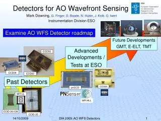
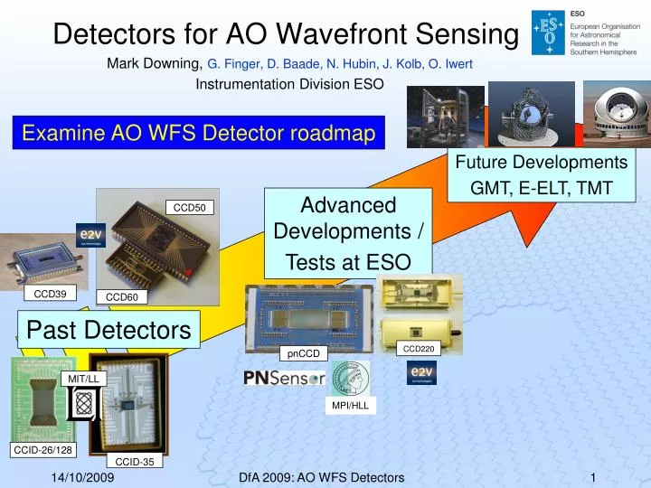
Future Developments GMT, E-ELT, TMT . Advanced Developments / Tests at ESO. Past Detectors. CCID-35. CCID-26/128. CCD50. pnCCD. CCD220. CCD60. Examine AO WFS Detector roadmap. Detectors for AO Wavefront Sensing. CCD39. Mark Downing, G. Finger, D. Baade, N. Hubin, J. Kolb, O. Iwert

E N D
Future Developments GMT, E-ELT, TMT Advanced Developments / Tests at ESO Past Detectors CCID-35 CCID-26/128 CCD50 pnCCD CCD220 CCD60 Examine AO WFS Detector roadmap Detectors for AO Wavefront Sensing CCD39 Mark Downing, G. Finger, D. Baade, N. Hubin, J. Kolb, O. Iwert Instrumentation Division ESO MIT/LL MPI/HLL DfA 2009: AO WFS Detectors
Adaptive Optics (AO) - removing the twinkle of the stars 1 Wavefronts from astronomical objects are distorted by the Earth’s atmosphere, reducing the spatial resolution of large telescopes to that of a 10 cm telescope Deformable mirror compensates the distorted wavefront, achieving diffraction-limited resolution OFF 4 ON 3 2 Wavefront Sensor measures deviation of wavefront from a flat (undistorted) wave Control System computes commands for the deformable mirror(s) DfA 2009: AO WFS Detectors
Challenge = Speed vs Noise Biggest challenge for AO WFS detectors is the trade between: • low noise (RON and dark current/count), and • fast frame rates • becomes more difficult as format sizes increase • and finally power dissipation limits feasibility It is instructive to review how this trade has been achieved in the past. DfA 2009: AO WFS Detectors
Read noise of output amplifier 5-10e- 100 k 10 k 1 M 10 M Amplifier Pixel Rate pix/sec e2v Add more outputs Achieves lower read noise at fast frame rates by reading through multiple outputs. More amplifiers DfA 2009: AO WFS Detectors
Improve the amplifier design Achieves lower read noise by designing better amplifiers. • Barry Burke (MIT/LL) CCID-56 160x160 21 µm pixel 20 outputs: • New pJFET amplifier design • Reporting ~ 2.5 e- at 1 Mpix/sec (800fps) • 256x256 by 21 µm pixel, 32/64 outputs in development RON • Type of amplifier (JFET or MOSFET, “p” or “n”). • Geometry (WxL) of amplifier. • Oxide thickness. • Reduce capacitances (floating diffusion and parasitic). • The higher the conversion gain the lower is the noise. Improve amplifier MIT/LL 100 k 10 k 1 M 10 M Amplifier Pixel Rate pix/sec e2v Refer back to talk by VyshnaviSuntharalingam, “Advanced Imager Technology Development at MIT Lincoln Laboratory” DfA 2009: AO WFS Detectors
If1 If2 If3 Rf1 Rf2 Rf3 Rf2HV Add EMCCD gain in the serial register Achieves lower read noise by adding electron multiplication register before the amplifier. Electron Multiplication Register E2v L3Vision: << 1 e- RON at output amplifier speeds of 16 Mpix/sec • CCD60 128x128 24 µm pixel. • 1,000 fps with 1 output. • CCD220 240x240 24 µm pixel. • 1,200 fps with 8 outputs. DfA 2009: AO WFS Detectors
Customize the architecture Achieves lower read noise by minimizing the number of pixels read out by custom designing the architecture to the application. Polar Co-ordinate CCD- talk about later Curvature CCD, CCID-35 – R. Dorn (ESO), J. Beletic, and B. Burke (MIT/LL). • 8x10 subapertues, • RON < 1.2e- at 4 kfps and QE > 80%, • Successfully used in upgrade to FlyEyes at CFHT. Buffer Image Area – 20x20 18µm pixels Serial register See poster Kevin Ho, “Flyeyes: Upgrade of CFHT’s AO System Using an MIT-LL CCID 35 Sensor” Array design Sub-aperture design MIT/LL Storage Area #2 Storage Area #1 DfA 2009: AO WFS Detectors
SPADA Add gain in the pixel => APD Achieves lower read noise by Electron Multiplication Gain in the pixel. • Build detector from array of single APDs or better an APD array. • Downside is silicon APDs have statistical variation of gain that results in an excess noise factor of ~ 2-3 • Overcome by operating the APD in high gain “Geiger” mode to discriminate and count single photon events and thus essentially offer zero read noise. e.g. PoliMI SPADA (Single Photon Avalanche Diode Arrays) • 80 APDs • QE ~ 40% • dark count rates < 3000 counts/sec/pixel • Photon counter → zero read noise at 20 kfps n p h e p+ substrate DfA 2009: AO WFS Detectors
MPI/HLL pnCCD E2v CCD220 FUNDING: OPTICON FP6-WFS SH 40 x 40 sub-ap. 6x6 pixels/sub-ap. 240x240 pixels VLT Instruments SPHERE, AOF – MUSE and HAWK-I Future Developments GMT, E-ELT, TMT Detectors for AO wavefront sensing Detectors in Advanced Development/ Test at ESO Mark Downing, G. Finger, D. Baade, N. Hubin, J. Kolb, O. Iwert ODT / Instrumentation Division ESO Past Detectors DfA 2009: AO WFS Detectors
OP 4 Gain Registers 8 L3Vision Gain Registers/Outputs Each 15Mpix./s. Metal Buttressed 2Φ 10 Mhz Clocks for fast image to store transfer rates. OP 3 OP 2 Gain Registers Store slanted to allow room for multiple outputs. OP 1 Image Area 240x120 24□µm Image Area 240x120 24□µm OP 8 OP 6 Gain Registers Gain Registers Store Area Store Area OP 7 OP 5 e2v CCD220 e2v CCD220: • Split frame transfer CCD • 240x240 24 µm pixels • 8 L3Vision EMCCD outputs • << 1 e- RON at1,200 fps FP6 Next talk Philippe Feautrier “OCam and CCD220 - World's Fastest and Most Sensitive Astronomical Camera” DfA 2009: AO WFS Detectors
Devices in house that meet specs. Technology transferred • ESO’s NGC WFS Camera Head is at advanced stage of prototype CCD220 Status Several Test Cameras in operation → built by LAM, LAOG, OHP Reported in Javier REYES poster “ESO AO Wavefront Sensor Camera” DfA 2009: AO WFS Detectors
MPI/HLL pnCCD(Robert Hartmann, Sebastian Ihle, Heike Soltau, Lothar Strueder) CAMEX 1 CAMEX 2 CAMEX 3 CAMEX 4 MPI/HLL Max Planck Institut /Halbleiterlabor pnCCD 256x256 pixels 51um pitch 450um thick fully depleted • excellent red response & no fringing • 300V backside bias for good PSF Target: RON < 3e- at 1000 fps Split frame transfer Fast readout → Column Parallel CCD • one output amplifier per column Total of 528 amplifiers but • CAMEX (mux 132 to 1) for easy I/F • Only 8 analog output nodes DfA 2009: AO WFS Detectors
pnCCD: Testing at ESO funded by OPTICON FP6→ Excellent QE, PSF, and low read noise Spot scanning used to measure PSF QE: • Excellent QE into the “Red” → good for Natural Guide Star applications. • 450 µm thick silicon is able to collect the deep penetrating red photons. PSF: • Measured < 0.45 pixel over 400-900nm (exceeds specs of < 0.8 pixel). • Pixels could be halved in size and still meet requirements. RON: • < 2.5 e-rms. 51µm Pixel FP6 FP6 DfA 2009: AO WFS Detectors
Development to add APD output → AApnCCD(Avalanche Amplified pnCCD)Part Funded by ESO and OPTICON FP6 Add avalanche stage before output amplifier Paper LotharStrüder MPE/HLL “Single Photon Counting in the Optical” FP6 MPI/HLL DfA 2009: AO WFS Detectors
AO WFS roadmap Detectors for AO wavefront sensing Future Developments GMT, E-ELT, TMT Detector in Advanced Development/ Test at ESO Mark Downing, G. Finger, D. Baade, N. Hubin, J. Kolb, O. Iwert ODT / Instrumentation Division ESO • Detectors required? • Top Level Requirements • Possible technologies Past Detectors DfA 2009: AO WFS Detectors
AO Detector needs for ELTs Low Order AO Shack Hartmann Quad -Cell IR WFS IR TipTilt sensors IR detectors development Pyramid Other WFS… NGS Ground LayerAO NGS Single Conjugate AO LGS Ground Layer AO TipTilt Sensors Guiding LGS Multi- Conjugate AO Laser Tomography AO Existing visible high performance detector (i.e. CCD220) Multi- ObjectAO Large visible fast low-noise detector for Shack-Hartmann based AO WFS Extreme AO 3kHz ultra low-noise detector DfA 2009: AO WFS Detectors
T ~ 10km Sodium layer H ~ 80km Predicted spot elongation pattern LLT Pupil plane Detector plane Distance from launch site Large Visible AO WFS Detector needed to sample the spot elongation Sodium Laser Guide Stars (589 nm) • AO systems operate at ~1 kHz frame rate • Bright “guide stars” are required • Only 1% of the sky is accessible with natural guide stars • Sodium layer at 80-90 km altitude can be stimulated to produce artificial guide stars anywhere on the sky • Pulsed laser can be used to range gate to limit laser spot elongation DfA 2009: AO WFS Detectors
Large Visible AO WFS Detector Top Level Requirements(developed from very detailed simulations) • Ease of use/compact size: integral Peltier digital I/F preferred DfA 2009: AO WFS Detectors
Large Visible AO WFS Detector Detector Plan (Multi-Phase Development) 2007 2008 2009 2010 2011 2012 2013 2014 2015 Several Design Studies • Investigated many different technologies • Most promising – CMOS Imager, APD array and orthogonal EMCCD Design Study Design Study Retire Pixel Risks Retire Architecture/ Process Risks Technology Validation TD Scaled Down Demonstrator Retire architectural risks by fab. ~ ¼ imager • Highly likely CMOS Usable device on Telescope Technology Demonstrator Full size device meeting all specs. SDD Scaled-down Demonstrator Several Technology Demonstrators • All CMOS Imagers - most likely to succeed • retire pixel risk by demonstration noise x speed with good imaging capability (no image lag) Full Scale Demonstrator Development Engineering exercise Authorize Production Testing/ Acceptance Testing Production Phase Production 30 Science Devices DfA 2009: AO WFS Detectors
supply supply voltage voltage reset reset 1 1 Read Read transfer transfer gate gate 2 2 4 4 3 3 FD FD PPD PPD column column output output With recent improvements CMOS now rival CCDs • Pinned Photo Diode→ low dark current (10 pA/cm2) • 0.5 e-/pix/frame with modest cooling (-10 DegC) • High conversion gains (200 µV/e-) → low RON of < 2e- • by reducing sense node capacitance < 0.8 fF • Buried channel MOSFETs → reduces/eliminates RTS signal noise • Build from thicker high resistivitysilicon and ‘substrate biasing’ • low crosstalk and good red response • Multi-sample the pixel at different conversion gains (µV/e-) • improves dynamic range and linearity PLUS the long offered advantages of • Fast frame rates → highly parallel readout: ultimate of amplifier per pixel. • Low power → µA instead of mA (CCD) transistor bias currents. • Monolithic integration of support circuitry; biases, sequencer, clocks, ADCs… Offers a simple, easy-to-use digital interface. DfA 2009: AO WFS Detectors
Custom orientate each pixel array to the LGS trajectory Read out fewer pixels Storage Area Imaging Area Image Clocks Storage Clocks Serial Register Polar Co-ordinate CCD Customizes CCD architecture to: • minimize no. of pixels to be read out • reduce image to store transfer time • conceived by Jim Beletic, Sean Akins of KECK; Barry Burke (MIT/LL) • being developed by Sean Akins, Brian Aull, Brad Felton (MIT/LL) • and Robert Reich) DfA 2009: AO WFS Detectors
Spot contained in much smaller number of pixels and only these need to be read out Na Layer Clock CCD charge with the spot Pulsed Laser Typical pixel array Clock annulus Laser projection point Typical subaperture Pulsed laser: track spot on CCD and move charge back and forth to collect photons from several pulses before reading out. • CCD needs to be customized: • for each new application, or • application configured or restricted to use existing CCD; e.g. use center projected laser and < 60x60 sub-apertures. • Scalability: • May not be scalable to 120x120 sub-apertures • 512 amplifiers could be challenging. 10 annuli clocked separately to optimally track spot DfA 2009: AO WFS Detectors
IR AO WFS Detectors Requirements • RON has limited use to low order Tip/Tilt and “Truth” sensors • Scientific detectors used: HAWAII-XRG (10e-) and the PICNIC (20e-) • For E-ELT much better detectors are needed: • e-APD • Teledyne Speedster Talk David Hale “Low-noise IR Wavefront Sensing with a Teledyne HxRG” DfA 2009: AO WFS Detectors
e-APDs • APDs in linear mode have excess noise factor, F > 1 • Typically 2-3 for silicon and 3-5 for III-V materials • In HgCdTe: F ~ 1in linear mode has been demonstrated • E.g. LETI: gain of 5300 and F ~ 1.05-1.3 at reverse bias of 12.5V. • impact ionization occurs mostly by single carrier, electrons, rather than the larger, slower, and less deterministic holes. • ESO has funded SELEX to develop a 24 µm 320x256 prototype detector: • λc = 2.5 µm • Prototype operational and initial results are encouraging. Several developments: see session on APDs on Thursday afternoon Ian BAKER (SELEX), “HgCdTe Avalanche Photodiode Arrays for Wavefront Sensing and Interferometry Applications”. Don Hall (IfA and Teledyne), “Electron-Avalanche and Hole-Avalanche HgCdTe Photodiode Arrays for Astronomy” Johan Rothman (CEA Leti-Minatec), “APD Development at CEA Leti-Minatec” DfA 2009: AO WFS Detectors
Teledyne Speedster Refer back to Jim Beletic’s talk “Teledyne Imaging Sensors - Producer of detectors with a dynamic range of 1 million....in several dimensions” • Speedster128 (designed 2005) • 128 x 128 pixels • 40 µm pixel pitch • Digital input – clocks and biases generated on-chip • Analog output • Two gain settings – high gain for lowest noise • Chip functionality and performance (in low gain) proven • High gain mode (which should be lowest noise) does not work as designed • Speedster256-D (designed 2008) • fix of Speedster128 design • Improved CTIA pixel • 256 x 256 pixels • 12 bit analog-to-digital converters on-board • Up to 10 kHz frame rate 27/6/2008 Detectors for AO WFS DfA 2009: AO WFS Detectors 25
Conclusion • Current detector developments at ESO are on track to meet current instrument needs. • Innovative detector developments are required for the ELTs. • ESO is actively involved with Detector Manufacturers to lay the foundations to meet these needs. DfA 2009: AO WFS Detectors
THANK YOU DfA 2009: AO WFS Detectors