Download
1 / 13
130 likes | 288 Views
Digital I/O. A group of I/O pins is called a PORT A port is where data enters/leaves the system. Digital I/O pins are usually grouped into 8,16 or 32-bit ports. A digital I/O port is normally accessed as a single entity through a register.

E N D
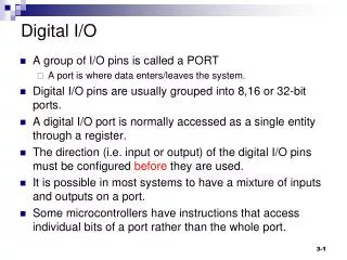
Digital I/O • A group of I/O pins is called a PORT • A port is where data enters/leaves the system. • Digital I/O pins are usually grouped into 8,16 or 32-bit ports. • A digital I/O port is normally accessed as a single entity through a register. • The direction (i.e. input or output) of the digital I/O pins must be configured before they are used. • It is possible in most systems to have a mixture of inputs and outputs on a port. • Some microcontrollers have instructions that access individual bits of a port rather than the whole port.
LPC23XX Functional Block Diagram The LPC2364/66/67/68 family The LPC2368 has 70 digital I/O pins , most pins have alternate functions. The default on reset is digital I/O
I/O pins and on-chip peripherals • Most I/O pins on microcontrollers have multiple functions. • The microcontroller must be configured to select the correct function. • The PINSEL registers control the functions of the device pins. TRACECLK TXD1 PWM1[1] GP I/O P2[0] 11 10 01 00 Function select bits (from the PINSEL register) PIN CONNECT BLOCK Physical I/O pin
Simple Digital I/O applications • Applications of General purpose I/O • Driving simple digital output devices such as LEDs, or other indicators. • Controlling off-chip devices. • Sensing digital input levels, detecting signal transitions. • Bringing the part out of Power Down modes. • Digital inputs can be configured to generate interrupts (the subject of a later lecture).
LPC2368 General purpose I/O • The LPC2368 has five 32-bit Ports (numbered 0 to 4) • Not all 32 bits are implemented in each port. See lpc23xx_um.pdf onBlackboard site TFBGA100 Package LQFP100 Package
LPC2368 General Purpose I/O The PORTS are accessed through specific registers. (These registers are memory locations that are defined in the header file LPC23XX.h) All the ports are accessible through FIO registers - these uses a fast internal bus operation. Each Port has its own set of FIO registers to setup, control and access the port. To maintain backwards compatibility with previous devices PORT0 and PORT1 are also accessible by an alternate set of registers - using a slower internal bus. We should use always use the FIO registers not the slower ones!
The FIO Registers Allow direction control of individual bits. An entire port value can be read or written in one instruction. Bit-level set and clear registers allow a single instruction set or clear of any number of bits in one port. Mask registers allow treating sets of port bits as a group, leaving other bits unchanged Remember all I/O pins default to input after reset.
Fast IO registers for PORT Access There are three additional registers that also influence access and control of the port (FIOSET,FIOCLR and FIOMASK) but the above two registers are all we need at present.
FIO Registers and Port DIRECTION • Setting port direction to OUTPUT • Set bits in FIOxDIR register ( 1 for output, 0 for input) • Examples: • FIO2DIR = 0x000000FF; //make PORT2 bits 0 to 7 output • FIO2DIR = 0x00000040; // make PORT2 bit 6 an output. Note this also makes bits 0-4 and 8-31 inputs (the default anyway) • If we want to only affect specific bits we can use masking:- • FIO2DIR |= 0x00000040; // only change bit 6 using OR • FIO2DIR |= (1 << 6); // simpler?
FIO Registers and Port DIRECTION • Setting port direction to INPUT • PORTS default to input on reset. • Set Direction using FIOxDIR (No harm in explicitly setting FIOxDIR) • Examples: • FIO2DIR = 0x00000000; // make ALL bits inputs (the default after a reset) • FIO2DIR &= 0xFFFFFB00; // make bit 10 an inputleave rest unchanged! • FIO2DIR &= ~0x00000400; // ? • FIO2DIR &= ~(1<<10); //
Polling input pins • Remember: All 32 bits are read on input • Isolate bits using masking e.g. for bit 10 • Wait for a bit to change • do{ x = FIO2PIN;} while((x & (1<<10)) == 0); //is bit 0? • while( (FIO2PIN & (1<<10)) == 0 ) //is bit 0? • while( (FIO2PIN & (1<<10)) != 0 ) //is bit 1? • test bit • if (FIO2PIN & (1<<10) == 0) • if (FIO2PIN & (1<<10) != 0)
Using ports in our programs • In the 'C' program include the special system header file for the LPC2368 processor which defines ALL the special register locations:- • #include <LPC23xx.H> • Configure the direction for the I/O pins before they are used (this is usually done just once at the beginning of the program). • Use the relevant FIOxPIN register to perform the I/O. Note the position in relation to the "=" • Output FIO2PIN = expr ; // on LHS of = • Input var = FIO2PIN; // on RHS of = Note: For input we usually need a variable to store the inputted value.
Program fragment #include <LPC23xx.H> // LPC23xx definitions int main (void) { Port2Init(); while(1) { FIO2PIN |= 0x000000FF; Delay(); FIO2PIN |= ~0x000000FF; Delay(); } } void Port2Init(void) { PINSEL10 = 0; // Disable ETM interface, enable LEDs FIO2DIR = 0x000000FF; // P2.0..7 defined as Outputs FIO2MASK = 0x00000000; // Unmask all port bits } //Delay function not shown.