Download
1 / 18
180 likes | 189 Views
DCDC design and implementation. F.Faccio, G.Blanchot, S.Michelis, C.Fuentes, B.Allongue, S.Orlandi CERN – PH-ESE S.Buso, G.Spiazzi PEL, DEI, University of Padova (I). Outline. Proposed scheme using DC-DC converters Conversion stage 1 Semiconductor technology Inductor design

E N D
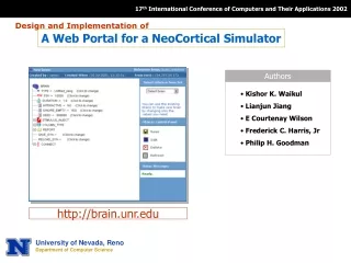
DCDC design and implementation F.Faccio, G.Blanchot, S.Michelis, C.Fuentes, B.Allongue, S.Orlandi CERN – PH-ESE S.Buso, G.Spiazzi PEL, DEI, University of Padova (I)
Outline Proposed scheme using DC-DC converters Conversion stage 1 Semiconductor technology Inductor design EMC (conducted and radiated noise) ASIC design Integration Conversion stage 2 (on-chip) Different conversion ratios Efficiency and area Conclusion F.Faccio, PH/ESE
Proposed distribution scheme (ATLAS Short Strip concept) Rod/stave 10-12V Voltage for SC and optoelectronics generated locally by a converter stage 1 2 Converter stage2 on-chip • Scheme based on 2 conversion stations: • Stage 1 at the module level • Stage 2 on-chip Summary of features • Modular approach, very flexible – building blocks can be custom assembled following system requirements • Each module turned on-off independently by SC • Each FE chip turned on-off independently by HC • Easy, gradual detector turn on procedure • Conventional grounding scheme • Conventional detector powering • Very efficient to provide only required power to every system component, at appropriate voltage Detector Hybrid controller Intermediate voltage bus(ses) 10-12V Converter stage 1 block F.Faccio, PH/ESE
2.0V power bus 2.5V power bus 1.8V power bus Serial “chip enable” bus from HC Serial “chip enable” bus from HC DC-DC DC-DC HC HC Serial “module enable” bus from SC Serial “module enable” bus from SC 10-12V 10-12V Implementation examples Dual Scheme • 2 converters in stage1 (analog and digital Intermediate bus) • Efficiency 80-85% • 2 converters in stage2 • Switched caps converters • Ratio ½ • Efficiency up to 95% • More efficient (up to 80% on stave) • More volume for stage 1 • Less area for on-chip converters Single Scheme • 1 converter in stage1 • Efficiency 80-85% • 2 converters in stage2 • Switched caps converters • Ratio ½ and 2/3 • Efficiency up to 95%, but possible presence of linear regulator might require drop with impact of 3-4% • Slightly less efficient • ½ of the volume for stage 1 • More area for on-chip converters, + 1 off-chip capacitor for each FE chip F.Faccio, PH/ESE
Outline Proposed scheme using DC-DC converters Conversion stage 1 Semiconductor technology Inductor design EMC (conducted and radiated noise) ASIC design Integration Conversion stage 2 (on-chip) Different conversion ratios Efficiency and area Conclusion F.Faccio, PH/ESE
Semiconductor technology (1) • The converter requires the use of a technology offering both low-voltage and high-voltage (15-20V) transistors • Properties of high-voltage transistors largely determine converter’s performance • Need for small Ron, and small gate capacitance (especially Cgd) for given Ron! • Survey of available options covered 5 technologies • Best results with 0.25um SGB25V GOD technology from IHP Prototype in 0.35mm F.Faccio, PH/ESE
Semiconductor technology (2) X-ray irradiation (TID) up to 350Mrd • Manageable Vth shift • Small or no leakage current increase • Ron decrease <20% (NMOS) and <40% (PMOS) NMOS, switching bias PMOS, WC bias Proton irradiation (displacement) up to 1016 p/cm2 • Negligible Vth shift • No leakage current increase • At 5∙1015 p/cm2, Ron decrease <60% (NMOS) and <80% (PMOS) PMOS, floating bias F.Faccio, PH/ESE NMOS, floating bias
Semiconductor technology (3) • One technology (0.25mm node) has demonstrated radiation tolerance compatible with benchmark: • NMOS Ron decrease below 60% for 2.5∙1015 n/cm2 (1MeV equivalent) • Vth shift manageable (below 200mV for NMOS, 400mV for PMOS @ 350Mrd) • Negligible leakage current with TID • Overall, radiation could affect converter performance as small drop of efficiency (below 5%) • One technology (0.13mm node) could satisfy requirements for installation further from collision point, where fluence is limited below 1∙1015 n/cm2 (1MeV equivalent) • The other 2 technologies are less performant and will not be considered further • Conclusion: • While starting prototype work in the 0.25um technology, another 0.18mm technology will be tested in 2009 (we look for a second source with comparable radiation performance) F.Faccio, PH/ESE
Inductor design: requirements • Coreless (no ferromagnetic material) • Value: up to 500-700nH (this is feasible with air-core) • Compact for high integration • Light for low material budget • With small ESR both in DC and AC (at the switching frequency) for high efficiency • It needs to be shielded for low radiated noise F.Faccio, PH/ESE
“Optimized” PCB toroid (1) • Custom design exploiting PCB technology: easy to manufacture, characteristics well reproducible • Design can be optimized for low volume, low ESR, minimum radiated noise • With the help of simulation tools (Ansoft Maxwell 3D and Q3D Extractor), we estimated inductance, capacitance and ESR for different designs. This guided the choice of the samples to manufacture as prototypes • The addition of two Al layers (top, bottom) shields the parasitic radiated field efficiently F.Faccio, PH/ESE
Toroid not shielded solenoid Noise floor Shielded toroid “Optimized” PCB toroid (2) • First samples manufactured at the CERN PCB shop • Inductance, shield efficiency, ESR in agreement with simulation • ESR can be decreased still by 2x by “filling” the vias – this has not yet been done • Now that the concept has been validated, we prepare for a prototype run with all the final characteristics (ESR, volume, shield material) Measurement in the lab: Normalized current induced in 1 Cu loop at increasing distance from the inductor (cm) F.Faccio, PH/ESE
EMC: conducted noise • 4 generations of converter prototypes using discrete commercial components developed • Aim: • Understand noise sources • Study and verify appropriate countermeasures • Provide experiments with hardware for integration studies • Develop know-how for final integration • Large decrease of noise observed • With small pi-filters, noise level meets class-B requirements of CISPR11 (voltage on line and neutral) Output common mode noise (current) measured with the CERN-ESE standard test bench for prototypes 3 and 5 (difference: layout of the board, and presence of pi-filters in proto5) F.Faccio, PH/ESE
ASIC development – 2nd generation • Second generation prototype • Still manufactured in AMIS 0.35mm • Features: • VIN and Power Rail Operation from +3.3V to +12V • Selectable output voltage (nominal 2.5V) • Maximum output current: 3A • Fast Transient Response - 0 to 100% Duty Cycle • 14MHz Bandwidth Error Amplifier with 10V/μs Slew Rate • Internal oscillator fixed at 1Mhz, programmable from 400kHz to 3MHz with external resistor • Internal voltage reference (nominally (1.2V) • Remote Voltage Sensing with Unity Gain • Programmable delay between gate signals • Integrated feedback loop with bandwidth of 20Khz • Submitted December 08, expected back in April 09 • Mounted in 7x7mm QFN package • Third generation will be in the IHP 0.25mm technology • It will be a simple buck • Refined comparison with 2-phase interleaved with V-divider (alternative topology), using also prototypes, has indicated little advantage of this latter topology at the small load currents foreseen for a module F.Faccio, PH/ESE
Dual Scheme: 2 converters (analog and digital power) INDUCTOR SMD SMD SMD ASIC SMD 1.5-2 cm Integration in ATLAS SCT module design From D.Ferrere University of Geneva 1.5-2 cm Towards integration • Compact design • Reducing the size of the full converter • Components: • ASIC (5x5 or 7x7 mm) • Inductor (4mm thick, 8-14mm diameter) • SMD components • Design compatible with tracker layout (evolving) in terms of area, volume, material budget, cooling F.Faccio, PH/ESE
Outline Proposed scheme using DC-DC converters Conversion stage 1 Semiconductor technology Inductor design EMC (conducted and radiated noise) ASIC design Integration Conversion stage 2 (on-chip) Different conversion ratios Efficiency and area Conclusion F.Faccio, PH/ESE
F2 Vin F1 Vout F2 Vin F1 Vout F2 F1 F2 F1 F2 F2 F1 Different conversion ratios ½ Conversion 2/3 Conversion 1 “flying” capacitor 1 output capacitor 4 switches 2 “flying” capacitors 1 output capacitor 7 switches F.Faccio, PH/ESE
Efficiency Freq (Hz) Rout (W) Efficiency, area Efficiency: • Analytical model developed and integrated in mathcad for conversion ratio ½ • It allows for estimating efficiency vs Rout and Frequency • Good agreement with Spice simulation in IBM 130nm technology (using I/O transistors) • Same work planned for conversion ratio 2/3 Area: • Estimate of on-chip area • Dependent on required efficiency • In the IBM 130nm technology, using I/O transistors, and for an efficiency ≥90%, it can be of the order of • 200x100 mm for ratio ½ • 200x200 mm for ratio 2/3 • Off-chip capacitors • Size around 100-200 nF looks appropriate Example: Efficiency for a converter ½ in IBM 130nm technology Vin=1.9V, Vout=0.93V, Iout=60mA, C=100nF F.Faccio, PH/ESE
Conclusion • Power distribution using DCDC converters is conventional and very flexible • System can be “customized” using a set of building blocks (buck converter for stage 1, switched capacitor converters on-chip, possibly even linear regulators) • Main difficulties in the development of a custom buck converter for stage 1 are being solved • Semiconductor technology satisfying radiation requirements has been found • Inductor design has been optimized and experimentally verified • Techniques for ASIC design are being learnt, and first prototypes have been developed • Large progress in understanding noise issues has been made and verified on prototypes (meeting class B requirements) • Main focus of our activity for 2009: • Design of the ASIC buck converter in the IHP 0.25mm technology • Integration of ASIC, PCB inductor and SMD components in compact DCDC converter boards representative of the final integration level achievable • Improve understanding and working tools for switched capacitor converters (especially ratio 2/3). Further involvement will depend on the activity of other groups F.Faccio, PH/ESE