Download
1 / 20
200 likes | 301 Views
Explore the concepts and methods of routing in electronic data networks using packet switching technology. Learn about the establishment of routing tables, advertisement methods, and delivery semantics such as unicast, broadcast, multicast, and anycast. Discover how IP multicast optimizes communication for one-to-many scenarios over an IP infrastructure.

E N D
The Routing Process Routing Table Establishment Routing Advertisement Methods
What is Routing? • Routing (or routeing) is the process of selecting paths in a network along which to send network traffic. Routing is performed for many kinds of networks, including the telephone network (Circuit switching) , electronic data networks (such as the Internet), and transportation networks. This article is concerned primarily with routing in electronic data networks using packet switching technology. • In packet switching networks, routing directs packet forwarding, the transit of logically addressed packets from their source toward their ultimate destination through intermediate nodes; typically hardware devices called routers, bridges, gateways, firewalls, or switches. General-purpose computers can also forward packets and perform routing, though they are not specialized hardware and may suffer from limited performance. The routing process usually directs forwarding on the basis of routing tables which maintain a record of the routes to various network destinations. Thus, constructing routing tables, which are held in the router's memory, is very important for efficient routing. Most routing algorithms use only one network path at a time, but multipath routing techniques enable the use of multiple alternative paths. • Routing, in a more narrow sense of the term, is often contrasted with bridging in its assumption that network addresses are structured and that similar addresses imply proximity within the network. Because structured addresses allow a single routing table entry to represent the route to a group of devices, structured addressing (routing, in the narrow sense) outperforms unstructured addressing (bridging) in large networks, and has become the dominant form of addressing on the Internet, though bridging is still widely used within localized environments.
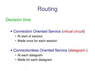
Delivery Semantics • Routing schemes differ in their delivery semantics: • Unicast delivers a message to a single specified node; • Broadcast delivers a message to all nodes in the network; • Multicast delivers a message to a group of nodes that have expressed interest in receiving the message; • Anycastdelivers a message to any one out of a group of nodes, typically the one nearest to the source. • Unicast is the dominant form of message delivery on the Internet, and this article focuses on unicast routing algorithms.
Anycast • Anycast is a network addressing and routing methodology in which datagrams from a single sender are routed to the topologically nearest node in a group of potential receivers all identified by the same destination address.
Broadcasting • In computing, broadcasting refers to a method of transferring a message to all recipients simultaneously. Broadcasting can be performed as a high level operation in a program, for example broadcasting Message Passing Interface, or it may be a low level networking operation, for example broadcasting on Ethernet.
Multicast • In computer networking, multicast is the delivery of a message or information to a group of destination computers simultaneously in a single transmission from the source creating copies automatically in other network elements, such as routers, only when the topology of the network requires it. • Multicast is most commonly implemented in IP multicast, which is often employed in Internet Protocol (IP) applications of streaming media and Internet television. In IP multicast the implementation of the multicast concept occurs at the IP routing level, where routers create optimal distribution paths for datagrams sent to a multicast destination address. • At the Data Link Layer, multicast describes one-to-many distribution such as Ethernet multicast addressing, Asynchronous Transfer Mode (ATM) point-to-multipoint virtual circuits (P2MP) or Infiniband multicast.
IP Multicast • IP multicast is a technique for one-to-many communication over an IP infrastructure in a network. It scales to a larger receiver population by not requiring prior knowledge of who or how many receivers there are. Multicast uses network infrastructure efficiently by requiring the source to send a packet only once, even if it needs to be delivered to a large number of receivers. The nodes in the network take care of replicating the packet to reach multiple receivers only when necessary. • The most common transport layer protocol to use multicast addressing is User Datagram Protocol (UDP). By its nature, UDP is not reliable—messages may be lost or delivered out of order. Reliable multicast protocols such as Pragmatic General Multicast (PGM) have been developed to add loss detection and retransmission on top of IP multicast. • IP multicast is widely deployed in enterprises, commercial stock exchanges, and multimedia content delivery networks. A common enterprise use of IP multicast is for IPTV applications such as distance learning and televised company meetings
Unicast • In computer networking, unicast transmission is the sending of messages to a single network destination identified by a unique address.
Topology Distribution • Small networks may involve manually configured routing tables (static routing) or non-adaptive routing, while larger networks involve complex topologies and may change rapidly, making the manual construction of routing tables unfeasible. Nevertheless, most of the public switched telephone network (PSTN) uses pre-computed routing tables, with fallback routes if the most direct route becomes blocked (see routing in the PSTN). Adaptive routing or dynamic routing attempts to solve this problem by constructing routing tables automatically, based on information carried by routing protocols, and allowing the network to act nearly autonomously in avoiding network failures and blockages. • For (static routing) or Non-Adaptive routing there is no algorithm, and is manually engineered. The advantage of this routing type is maximum computing resources are saved but are conditioned. Networks have to be prepared for disaster, by additional planning. For larger networks, static routing is avoided. • Examples for (Dynamic routing) or Adaptive routing algorithms are Routing Information Protocol(RIP), Open Shortest Path First(OSPF). Dynamic routing dominates the Internet. However, the configuration of the routing protocols often requires a skilled touch; one should not suppose that networking technology has developed to the point of the complete automation of routing.
Distance Vector Algorithms • Distance vector algorithms use the Bellman-Ford algorithm. This approach assigns a number, the cost, to each of the links between each node in the network. Nodes will send information from point A to point B via the path that results in the lowest total cost (i.e. the sum of the costs of the links between the nodes used). • The algorithm operates in a very simple manner. When a node first starts, it only knows of its immediate neighbours, and the direct cost involved in reaching them. (This information, the list of destinations, the total cost to each, and the next hop to send data to get there, makes up the routing table, or distance table.) Each node, on a regular basis, sends to each neighbour its own current idea of the total cost to get to all the destinations it knows of. The neighbouring node(s) examine this information, and compare it to what they already 'know'; anything which represents an improvement on what they already have, they insert in their own routing table(s). Over time, all the nodes in the network will discover the best next hop for all destinations, and the best total cost. • When one of the nodes involved goes down, those nodes which used it as their next hop for certain destinations discard those entries, and create new routing-table information. They then pass this information to all adjacent nodes, which then repeat the process. Eventually all the nodes in the network receive the updated information, and will then discover new paths to all the destinations which they can still "reach".
Link-state Algorithms • When applying link-state algorithms, each node uses as its fundamental data a map of the network in the form of a graph. To produce this, each node floods the entire network with information about what other nodes it can connect to, and each node then independently assembles this information into a map. Using this map, each router then independently determines the least-cost path from itself to every other node using a standard shortest paths algorithm such as Dijkstra's algorithm. The result is a tree rooted at the current node such that the path through the tree from the root to any other node is the least-cost path to that node. This tree then serves to construct the routing table, which specifies the best next hop to get from the current node to any other node.
Optimized Link State Routing Algorithm • A link-state routing algorithm - optimized for mobile ad-hoc networks is the Optimized Link State Routing Protocol (OLSR).[1] OLSR is proactive, it uses Hello and Topology Control (TC) messages to discover and disseminate link state information into the mobile ad-hoc network. Using Hello messages each node discovers 2-hop neighbor information and elects a set of multipoint relays (MPRs). MPRs makes OLSR unique from other link state routing protocols. Individual nodes use the topology information to compute next hop paths regard to all nodes in the network utilising shortest hop forwarding paths.
Path Vector Protocol • Distance vector and link state routing are both intra-domain routing protocols. They are used inside an autonomous system, but not between autonomous systems. Both of these routing protocols become intractable in large networks and cannot be used in Inter-domain routing. Distance vector routing is subject to instability if there are more than a few hops in the domain. Link state routing needs huge amount of resources to calculate routing tables. It also creates heavy traffic because of flooding.
Path Vector Protocol • Path vector routing is used for inter-domain routing. It is similar to distance vector routing. In path vector routing we assume there is one node (there can be many) in each autonomous system which acts on behalf of the entire autonomous system. This node is called the speaker node. The speaker node creates a routing table and advertises it to neighboring speaker nodes in neighboring autonomous systems. The idea is the same as distance vector routing except that only speaker nodes in each autonomous system can communicate with each other. The speaker node advertises the path, not the metric of the nodes, in its autonomous system or other autonomous systems. Path vector routing is discussed in RFC 1322; the path vector routing algorithm is somewhat similar to the distance vector algorithm in the sense that each border router advertises the destinations it can reach to its neighboring router. However, instead of advertising networks in terms of a destination and the distance to that destination, networks are advertised as destination addresses and path descriptions to reach those destinations. A route is defined as a pairing between a destination and the attributes of the path to that destination, thus the name, path vector routing, where the routers receive a vector that contains paths to a set of destinations. The path, expressed in terms of the domains (or confederations) traversed so far, is carried in a special path attribute that records the sequence of routing domains through which the reachability information has passed.
Comparison of Routing Algorithms • Distance-vector routing protocols are simple and efficient in small networks, and require little, if any management. However, distance-vector algorithms do not scale well (due to the count-to-infinity problem), have poor convergence properties and are based on a 'hop count' metric rather than a 'link-state' metric thus they ignore bandwidth (a major drawback) when calculating the best path. • This has led to the development of more complex but more scalable algorithms for use in large networks. Interior routing mostly uses link-state routing protocols such as OSPF and IS-IS. • A more recent development is that of loop-free distance-vector protocols (e.g. EIGRP). Loop-free distance-vector protocols are as robust and manageable as distance-vector protocols, while avoiding counting to infinity and hence having good worst-case convergence times.
Path Selection • Path selection involves applying a routing metric to multiple routes, in order to select (or predict) the best route. • In the case of computer networking, the metric is computed by a routing algorithm, and can cover such information as bandwidth, network delay, hop count, path cost, load, MTU, reliability, and communication cost. The routing table stores only the best possible routes, while link-state or topological databases may store all other information as well. • Because a routing metric is specific to a given routing protocol, multi-protocol routers must use some external heuristic in order to select between routes learned from different routing protocols. Cisco's routers, for example, attribute a value known as the administrative distance to each route, where smaller administrative distances indicate routes learned from a supposedly more reliable protocol. • A local network administrator, in special cases, can set up host-specific routes to a particular machine which provides more control over network usage, permits testing and better overall security. This can come in handy when required to debug network connections or routing tables.
Multiple Agents • In some networks, routing is complicated by the fact that no single entity is responsible for selecting paths: instead, multiple entities are involved in selecting paths or even parts of a single path. Complications or inefficiency can result if these entities choose paths to optimize their own objectives, which may conflict with the objectives of other participants. • A classic example involves traffic in a road system, in which each driver picks a path which minimizes their own travel time. With such routing, the equilibrium routes can be longer than optimal for all drivers. In particular, Braess paradox shows that adding a new road can lengthen travel times for all drivers.
Multiple Agents Cont. • The Internet is partitioned into autonomous systems (ASs) such as internet service providers (ISPs), each of which has control over routes involving its network, at multiple levels. First, AS-level paths are selected via the BGP protocol, which produces a sequence of ASs through which packets will flow. Each AS may have multiple paths, offered by neighboring ASs, from which to choose. Its decision often involves business relationships with these neighboringASs, which may be unrelated to path quality or latency. Second, once an AS-level path has been selected, there are often multiple corresponding router-level paths, in part because two ISPs may be connected in multiple locations. In choosing the single router-level path, it is common practice for each ISP to employ hot-potato routing: sending traffic along the path that minimizes the distance through the ISP's own network—even if that path lengthens the total distance to the destination. • Consider two ISPs, A and B, which each have a presence in New York, connected by a fast link with latency 5 ms; and which each have a presence in London connected by a 5 ms link. Suppose both ISPs have trans-Atlantic links connecting their two networks, but A's link has latency 100 ms and B's has latency 120 ms. When routing a message from a source in A's London network to a destination in B's New York network, A may choose to immediately send the message to B in London. This saves A the work of sending it along an expensive trans-Atlantic link, but causes the message to experience latency 125 ms when the other route would have been 20 ms faster.
Route Analytics • As the Internet and IP networks become mission critical business tools, there has been increased interest in techniques and methods to monitor the routing posture of networks. Incorrect routing or routing issues cause undesirable performance degradation, flapping and/or downtime. Monitoring routing in a network is achieved using Route analytics tools and techniques