Download
1 / 48
490 likes | 524 Views
Learn how to construct circuits from logic gates to perform operations like checking equality and addition of numbers. Understand the relationship between circuit diagrams and Boolean expressions for accurate output. Follow the step-by-step Sum-of-Products algorithm to design circuit layouts effectively.

E N D
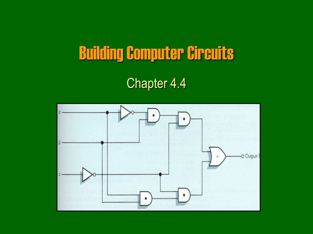
Building Computer Circuits Chapter 4.4
Purpose • We have looked at so far how to build logic gates from transistors. • Next we will look at how to build circuits from logic gates, for example: • A circuit to check if two numbers are equal. • A circuit to add two numbers. • Gates will become our new building blocks: • Human body: cells organs body • Computers: gates circuits computer (c) Yngvi Bjornsson
Circuit • A circuit is a collection of interconnected logic gates: • that transforms a set of binary inputs into a set of binary outputs, and • where the values of the outputs depend only on the current values of the inputs • These kind of circuits are more accurately calledcombinatorial circuits. (c) Yngvi Bjornsson
Circuit (external view) • A circuit can have any number of inputs and outputs: • Number of inputs and outputs can differ. • The inputs and outputs are either 0 or 1. (c) Yngvi Bjornsson
0 0 0 1 0 1 1 1 1 0 1 1 1 0 1 1 Circuit (external view cont.) • Output depends only on current input values • Each set of input always generates the same output. • Different sets of input can generate identical output. CIRCUIT OUTPUT INPUT (c) Yngvi Bjornsson
Circuit (internal view) • Circuits are build from interconnected AND, OR and NOT gates, in a way such that each input combination produces the desired output. (c) Yngvi Bjornsson
1 Example • What are the output values c and d given input values a=1, b=0? a 1 c 0 0 b d (c) Yngvi Bjornsson
Circuit Diagrams and Boolean Expressions • The diagrams we were looking at are called circuit diagrams. • Relationship between circuit diagrams and Boolean expr.: • Every Boolean expression can be represented pictorially as a circuit. • Every output in a circuit diagram can be written as a Boolean expression. • Example (output values c and d from previous diagram): • c = ( a OR b) • d = NOT ( (a OR b) AND (NOT b) ) (c) Yngvi Bjornsson
(a OR b) AND (NOT b) (NOT b) Circuits Diagram and Boolean Expressions • Deriving Boolean expressions for the output. a (a OR b) (a OR b) NOT ((a OR b) AND (NOT b)) b (c) Yngvi Bjornsson
a (a + b) (a + b) (a + b) · b (a + b) · b b b Circuits Diagram and Boolean Expressions • Remember, when writing Boolean expressions for circuit diagrams, we use a different notation! (c) Yngvi Bjornsson
a·b + a·b a a·b b Example • What Boolean expression describes the output? a a·b b (c) Yngvi Bjornsson
Constructing Circuits • How do we design and construct circuits? • We first have to know what we want the circuit to do! • This implies, that for all possible input combinations we must decide what the output should be. • Once we know that, there exists methods we can use to design the layout of the circuit. • We will look at one such method called, sum-of-products algorithm. (c) Yngvi Bjornsson
Sum-of-Products Algorithm Step 1: Truth Table Construction Repeat steps 2, 3 and 4 for each output column Step 2: Sub-expression construction using AND and NOT gates Step 3: Sub-expression combination using OR gates Step 4: Circuit Diagram Production Step 5: Combine Circuit Diagrams Step 6: Optimize Circuit (optional) Step 7: Stop (c) Yngvi Bjornsson
0 0 1 0 0 0 0 1 0 0 Circuit Step 1: Truth Table Construction • Decide what the circuit is supposed to do: • treat the circuit itself as a “black box” • only interested in input/output signals (c) Yngvi Bjornsson
3 inputs 23 = 8 possibilities Step 1 (cont.) • Write the desired output for all possible input combinations: (c) Yngvi Bjornsson
Case 1 Case 2 Step 2: Sub-expression Construction • For each output (separately): • Use AND and NOT gates to construct a sub-expression for rows where the output is 1 (c) Yngvi Bjornsson
a·b·c a·b·c Step 2 (cont.) • Look at the inputs, if the value is • 1 then use input as is in sub-expression, ( e.g. b ) • 0 then use input value complemented ( e.g. a ) • Why do it this way? • Each expression will evaluate to 1 for given input combination (row), but 0 for all other inputs! (c) Yngvi Bjornsson
( a·b·c ) + ( a·b·c ) Step 3: Sub-expression Combination • Use OR gates to combine the sub-expressions from previous step into one expression • This expression will evaluate to 1 for all input combinations that have 1 as output, but 0 for all the other input combinations (rows)! (c) Yngvi Bjornsson
( a·b·c ) + ( a·b·c ) a b c Step 4: Circuit Diagram Production • Construct a circuit diagram from the expression generated in previous step: (c) Yngvi Bjornsson
( a·b·c ) + ( a·b·c ) + ( a·b·c ) + ( a·b·c ) Repeat steps 2, 3, and 4 for each output • We need to repeat steps 2, 3, 4 for each output. • In our example, there is one more output: • Step2: Four sub-expressions, one for each row: • Step 3: Combine sub-expressions using + (OR): • Step 4: Draw circuit diagram a·b·c a·b·c a·b·c a·b·c • (see p. 694 in text-book) (c) Yngvi Bjornsson
a Circuit for Output 1 b Output 1 c Circuit for Output 2 Output 2 Combine Individual Circuits • Combine the circuits for each individual output into an one larger circuit. (c) Yngvi Bjornsson
Optimize the Circuit • A circuit build using this algorithm will generate the correct output, but it uses unnecessarily many gates • Why is that important? • Typically we need to optimize the circuit, by minimize the number of gates used. • An optimized circuit for the example would look like: (c) Yngvi Bjornsson
… = = = = Example 1: Compare-for-Equality Circuit (N-CE) • We want to build a circuit that checks if two numbers are the same? • The same number if and only if all corresponding bits are the identical. • First step is to build a circuit that compares two bits (can then use 16 of those to compare two 16-bit numbers!) (c) Yngvi Bjornsson
1-CE 0 0 1 Ex1 -- Step 1: Truth table construction • The circuit to compare two bits has: • two inputs (the value of the two bits) • one output (0 if the bits are different, 1 if the bits are same) • How does the truth-table look like? (c) Yngvi Bjornsson
a·b Example 1: Step 2 Construct sub-expressions • Construct a Boolean expression for each row in the table where the output is one: = = a·b (c) Yngvi Bjornsson
( a·b ) + ( a·b ) Example 1: Step 3 and 4 • Combine into one sub-expression using OR (+) • Draw a circuit diagram (c) Yngvi Bjornsson
Repeat for each output • Need to repeat step 2, 3, 4 for all outputs: • There is only one output, so we are done! • So our 1-bit compare circuit ( 1-CE ) looks like: • But we want to compare N-bit sized numbers? (c) Yngvi Bjornsson
N-bit compare a b 1 (c) Yngvi Bjornsson
Example 2: An Addition Circuit (N-add) • We want to build a circuit that adds two integers. • How do we add two binary numbers • the same way as decimal numbers (but different base) 1 1 1 a b + s 1 1 0 1 0 1 1 0 (c) Yngvi Bjornsson
0 carry = 1-ADD = carry 1 a = 1 = s 0 1 b = Example 2: 1-ADD • Let’s start by building a circuit that adds three bits (two bits + carry) • We can then use N of these 1-ADD circuits to add any two N-bit integers. (c) Yngvi Bjornsson
Ex2-- Step 1: Truth table construction (c) Yngvi Bjornsson
s = (a·b·c) + (a·b·c) + (a·b·c) + (a·b·c) a·b·c a·b·c a·b·c Example 2: Step 2-3 (output 1) • Construct a Boolean expression for each 1-row a·b·c • Combine into one Boolean expression (c) Yngvi Bjornsson
Example 2: Step 4 Circuit Diagram (output 1) (c) Yngvi Bjornsson
a·b·c a·b·c a·b·c s = ( a·b·c ) + ( a·b·c ) + ( a·b·c ) + ( a·b·c ) Example 2: Step 2-3-4 (output 2) • Step2 : Construct a Boolean expression for each 1-row a·b·c • Step 3: Combine into one Boolean expression • Step 4: Draw a circuit diagram (not shown) (c) Yngvi Bjornsson
Example 2: Combining output 1 and 2 circuits s carry (c) Yngvi Bjornsson
Example 2: N-ADD (c) Yngvi Bjornsson
Example 2: Optimize the circuit • Each 1-ADD circuit has 25 gates (47 transistors) • 16 AND gates ( x 2 transistors) • 6 OR games ( x 2 transistors) • 3 NOT gates ( x 1 transistors) • To add two 32-bits bits integers we need • 32 1-ADD circuits 32 * 25 = 800 gates 1504 transistors • Optimized 32-bits addition circuit in modern computers uses: 500-600 transistors • We will not learn how to optimize circuits in this course (c) Yngvi Bjornsson
Control Circuits Chapter 4.5
Control Circuits • So far we have seen two types of circuits: • Logical ( is a = b ?) • Arithmetic ( c = a + b) • Computers use many different logical (>, <, >=. <=, !=, …), and arithmetic (+,-,*,/) circuits. • There are also different kind of circuits that are essential for computers control circuits • We will look at two different kind of control circuits, multiplexors and decoders. (c) Yngvi Bjornsson
Multiplexor • A multiplexor circuit has: • 2N input lines (numbered 0, …, 2N-1) • 1 output line • N selector lines • The selector lines are used to choose which of the input signals becomes the output signal: • Selector lines interpreted as an N-bit integer • The signal on the input line with the corresponding number becomes the output signal. (c) Yngvi Bjornsson
Multiplexor (cont.) (c) Yngvi Bjornsson
Multiplexor 0 1 0 1 1 0 1 0 0 0 0 1 1 1 0 1 Multiplexor (cont.) 0 1 2 3 (c) Yngvi Bjornsson
Decoder • A decoder circuit has: • N input lines (numbered 0, 1, …., N-1) • 2N output line (numbered 0, 1, … 2N-1) • Works as follows: • The N input lines are interpreted as a N-bit integer value. • The output line corresponding to the integer value is set to 1, all other to 0 (c) Yngvi Bjornsson
Decoder (cont.) (c) Yngvi Bjornsson
Decoder (cont.) 0 Decoder 0 0 0 1 1 0 2 0 3 2 1 4 100 = 4 0 5 0 6 7 0 (c) Yngvi Bjornsson
Summary • We looked at how computers represent data: • Internal vs External Representation • Basic storage unit is a binary digit bit • Data is represented internally as binary data. • Use the binary number system. • We learned why computers use binary data: • Main reason is reliability • Electronic devices work best in bi-stable environment. (c) Yngvi Bjornsson
Summary (cont.) • We looked at the basic building blocks used in computers: • Binary Storage Device = Transistor • We saw how to build logic gates (AND, OR, NOT): • Transistors Gates • Boolean logic • We saw how to build circuits: • Gates Circuits • Looked at logical, arithmetic, and control circuits. (c) Yngvi Bjornsson
Summary (cont.) • Now that we have seen the basic building blocks (low-level view), in the next chapter we will look at the “big picture” (high-level view). • We will look at the basic architecture underlying design of all computers: • Look at higher level computer components, such as processors and memory. • Understand better how computers execute programs. (c) Yngvi Bjornsson