Download
1 / 151
1.53k likes | 1.69k Views
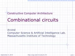
Logic Circuits and Computer Architecture. Appendix A Digital Logic Circuits Part 2: Combinational and Sequential Circuits. Combinational circuits. Each of the m outputs can be expressed as function of n input variables Truth table has: n input columns m output columns

E N D
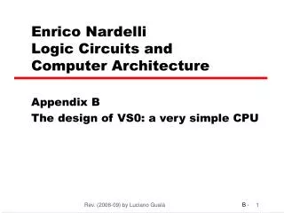
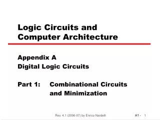
Logic Circuits and Computer Architecture Appendix A Digital Logic Circuits Part 2: Combinational and Sequential Circuits RLAC (2008-09) by Luciano Gualà
Combinational circuits • Each of the m outputs can be expressed as function of n input variables • Truth table has: • n input columns • m output columns • 2n rows (all possible input combinations) RLAC (2008-09) by Luciano Gualà
Binary Adder A=a3a2a1a0 C=c4c3c2c1c0 : the sum of A and B B=b3b2b1b0 b3 a3 b2 a2 b0 a0 b1 a1 Combinational Circuit c3 c2 c1 c4 c0 RLAC (2008-09) by Luciano Gualà
Seven-segment decoder It converts a 4-bit binary-coded decimal (BCD) value into the code required to drive a seven-segment display a a b c d e f g f b A B C D Combinational Circuit g c e d A=0 B=1 C=1 D=1 A=0 B=0 C=0 D=0 RLAC (2008-09) by Luciano Gualà
The truth table RLAC (2008-09) by Luciano Gualà
Design Procedure • Specification • Write a specification for the circuit if one is not already available • Formulation • Derive a truth table or initial Boolean equations that define the required relationships between the inputs and outputs, if not in the specification • Apply hierarchical design if appropriate • Optimization • Apply 2-level and multiple-level optimization • Draw a logic diagram or provide a netlist for the resulting circuit using ANDs, ORs, and inverters RLAC (2008-09) by Luciano Gualà
Design Procedure • Technology Mapping • Map the logic diagram or netlist to the implementation technology selected • Verification • Verify the correctness of the final design manually or using simulation RLAC (2008-09) by Luciano Gualà
Design Example • Specification • BCD to Excess-3 code converter • Transforms BCD code for the decimal digits to Excess-3 code for the decimal digits • BCD code words for digits 0 through 9: 4-bit patterns 0000 to 1001, respectively • Excess-3 code words for digits 0 through 9: 4-bit patterns consisting of 3 (binary 0011) added to each BCD code word • Implementation: • multiple-level circuit RLAC (2008-09) by Luciano Gualà
Input BCD Output Excess - 3 A B C D WXYZ 0 0 0 0 0 0 1 1 0 0 0 1 0 1 0 0 0 0 1 0 0 1 0 1 0 0 1 1 0 1 1 0 0 1 0 0 0 1 1 1 0 1 0 1 1 0 0 0 0 1 1 0 1 0 0 1 0 1 1 1 1 0 1 0 1 0 0 0 1 0 1 1 1 0 0 1 1 1 0 0 Design Example (continued) • Formulation • Conversion of 4-bit codes can be most easily formulated by a truth table • Variables- BCD: A,B,C,D • Variables- Excess-3 W,X,Y,Z • Don’t Cares- BCD 1010 to 1111 RLAC (2008-09) by Luciano Gualà
C C z y 1 1 1 1 0 1 3 2 0 1 3 2 1 1 1 1 4 5 7 6 4 5 7 6 B B X X X X X X X X 12 13 15 14 12 13 15 14 A A 1 X X 1 X X 8 9 11 10 8 9 11 10 D D x C C w 1 1 1 0 1 3 2 0 1 3 2 1 1 1 1 4 5 7 6 4 5 7 6 B B X X X X X X X X 12 13 15 14 12 13 15 14 A A 1 X X 1 1 X X 8 9 11 10 8 9 11 10 D D Design Example (continued) • Optimization • 2-level usingK-maps W = A + BC + BD X = B’C + B’D + BC’D’ Y = CD + C’D’ Z = D’ RLAC (2008-09) by Luciano Gualà
B C D D D B C Design Example (continued) • Optimization (continued) • Multiple-level optimization: we start fromW = A + BC + BDX = C + D + BY = CD + Z =G = 7 + 10 + 6 + 0 = 23 • …and we obtain: W = A + BT X = B’T + BC’D’ where T = C + D Y = CD + C’D’ Z = D’ G = 19 RLAC (2008-09) by Luciano Gualà
A W B X Y C D Z Design Example (continued) RLAC (2008-09) by Luciano Gualà
Beginning Hierarchical Design • To control the complexity of the function mapping inputs to outputs: • Decompose the function into smaller pieces called blocks • Decompose each block’s function into smaller blocks, repeating as necessary until all blocks are small enough • Any block not decomposed is called a primitive block • The collection of all blocks including the decomposed ones is a hierarchy • Example: comparison circuit for 4-bit words • Specification: • Input: vectors A(3:0) and B(3:0); Ai Bi: i-th element of A and B, respectively • Output: a variable E; E=1 if and only if A=B • Formulation: • is it convenient to derive the truth table? RLAC (2008-09) by Luciano Gualà
A0 A1 A2 A3 E B0 B1 B2 B3 Ni=0 iff Ai=Bi RLAC (2008-09) by Luciano Gualà
Reusable Functions • Whenever possible, we try to decompose a complex design into common, reusablefunction blocks • These blocks are • verified and well-documented • placed in libraries for future use RLAC (2008-09) by Luciano Gualà
Top-Down versus Bottom-Up • A top-down design proceeds from an abstract, high-level specification to a more and more detailed design by decomposition and successive refinement • A bottom-up design starts with detailed primitive blocks and combines them into larger and more complex functional blocks RLAC (2008-09) by Luciano Gualà
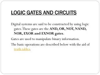
Functions and Functional Blocks • The functions considered are those found to be very useful in design • Corresponding to each of the functions is a combinational circuit implementation called a functional block • In the past, functional blocks were packaged as small-scale-integrated (SSI), medium-scale integrated (MSI), and large-scale-integrated (LSI) circuits. • Today, they are often simply implemented within a very-large-scale-integrated (VLSI) circuit. RLAC (2008-09) by Luciano Gualà
Real circuits • 74LS00 - has four 2-input NAND gates • Small scale integration (SSI) RLAC (2008-09) by Luciano Gualà
Integrated circuits • Scales of integration • (Small) SSI: 1-10 gates • (Medium) MSI: 10-100 gates • (Large) LSI: 100-100.000 gates • (Very Large) VLSI: > 100.000 gates RLAC (2008-09) by Luciano Gualà
Decoder (n-to-2n) • Convert n inputs to exactly one of 2n outputs i.e., given an n-bit value i in input the decoder activates only the i-th output line An example decoder 2-to-4 D0 0 A0 20 D1 1 A1 2 D2 21 3 D3 RLAC (2008-09) by Luciano Gualà
A D D 0 1 D A 0 0 1 0 1 0 1 D A A 1 Decoder Examples 1-to-2 decoder A 0 A A D D D D 1 0 0 1 2 3 A 1 0 0 1 0 0 0 D A A 0 1 0 0 1 0 1 0 0 1 0 0 0 1 0 D A A 1 1 0 0 0 1 1 1 0 (a) D A A 2 1 0 2-to-4 decoder RLAC (2008-09) by Luciano Gualà D A A 3 1 0 (b)
A 3-to-8 decoder RLAC (2008-09) by Luciano Gualà
a d b c a b equivalent to c d a d b c a b equivalent to c d A2 Inputs A1 A0 3-to-8 decoder … D0 D1 D7 RLAC (2008-09) by Luciano Gualà
A different circuit for a 3-to-8 decoder RLAC (2008-09) by Luciano Gualà
Decoder Expansion • General procedure for building a decoder with n inputs and 2n outputs • This procedure builds a decoder backward from the outputs • We take 2n 2-input AND gates (output AND gates) • The output AND gates are driven by two decoders with their numbers of inputs either equal or differing by 1 • These decoders are then designed using the same procedure until 1-to-2-line decoders are reached RLAC (2008-09) by Luciano Gualà
Decoder Expansion - Example 1 • 3-to-8-line decoder • Number of output ANDs = 8 • Number of inputs to decoders driving output ANDs = 3 • Closest possible split to equal • 2-to-4-line decoder • 1-to-2-line decoder • 2-to-4-line decoder • Number of output ANDs = 4 • Number of inputs to decoders driving output ANDs = 2 • Closest possible split to equal • Two 1-to-2-line decoders RLAC (2008-09) by Luciano Gualà
Decoder Expansion - Example 2 • 6-to-64-line decoder • Number of output ANDs = 64 • Number of inputs to decoders driving output ANDs = 6 • Closest possible split to equal • two 3-to-8-line decoders • 3-to-8-line decoder • Number of output ANDs = 8 • Number of inputs to decoders driving output ANDs = 3 • Closest possible split to equal • 2-to-4-line decoder • 1-to-2-line decoder • … RLAC (2008-09) by Luciano Gualà
+ 16 + 32 G= 0 + 128 = 176 RLAC (2008-09) by Luciano Gualà G= 64 * 6= 384 cost of a 2-level circuit:
Decoder with Enable • See truth table below for function • Note use of X’s to denote both 0 and 1 • Combination containing two X’s represent four binary combinations EN A A D D D D 1 0 0 1 2 3 0 X X 0 0 0 0 1 0 0 1 0 0 0 1 0 1 0 1 0 0 1 1 0 0 0 1 0 1 1 1 0 0 0 1 RLAC (2008-09) by Luciano Gualà
E S1 S0 RLAC (2008-09) by Luciano Gualà
decoder 2-to-4 decoder 2-to-4 0 0 20 20 1 1 2 2 21 21 3 3 Enable Enable 3-to-8 decoder from two 2-to-4 decoders with enable D0 A0 D1 A1 D2 D3 A2 D4 D5 D6 D7 RLAC (2008-09) by Luciano Gualà
Combinational Logic Implementation- Decoder and OR Gates • Implement m functions of n variables with: • Sum-of-minterms expressions • One n-to-2n-line decoder • mOR gates, one for each output • Approach 1: • Find the truth table for the functions • Make a connection to the corresponding OR from the corresponding decoder output wherever a 1 appears in the truth table • Approach 2 • Find the minterms for each output function • OR the minterms together RLAC (2008-09) by Luciano Gualà
F1 A0 A1 A2 A3 0 1 2 3 4 5 6 7 8 9 10 11 12 13 14 15 F2 F3 Decoder and OR Gates Example Finding sum ofminterms expressions F1 = m (1,2,5,6,8,11,12,15)F2 = m (1,3,4,6,8,10,13,15)F3 = m (2,3,4,5,8,9,14,15) RLAC (2008-09) by Luciano Gualà
Exercise • Use a decoder and or gates to build a combinatorial circuit with • INPUT: 3 boolean variables • OUTPUT: the number of 1s in the input (expressed in binary) RLAC (2008-09) by Luciano Gualà
Solution: Truth Table RLAC (2008-09) by Luciano Gualà
Solution: the implementation OR Gates A0 A1 A2 D1 D0 RLAC (2008-09) by Luciano Gualà
Encoding • Encoding - the opposite of decoding - the conversion of an m-bit input code to a n-bit output code with n£ m£ 2n such that each valid code word produces a unique output code • Circuits that perform encoding are called encoders • An encoder has 2n (or fewer) input lines and n output lines which generate the binary code corresponding to the input values • Typically, an encoder converts a code containing exactly one bit that is 1 to a binary code corresponding to the position in which the 1 appears. RLAC (2008-09) by Luciano Gualà
a truth table for a 8-to-3 encoder • A2 = D4 + D5 + D6 + D7 • A1 = D2 + D3 + D6 + D7 • A0 = D1 + D3 + D5 + D7 RLAC (2008-09) by Luciano Gualà
Encoder Example • A decimal-to-BCD encoder • Inputs: 10 bits corresponding to decimal digits 0 through 9, (D0, …, D9) • Outputs: 4 bits with BCD codes • Function: If input bit Di = 1, then the output (A3, A2, A1, A0) is the BCD code for i • Exercise: design and realize it RLAC (2008-09) by Luciano Gualà
Priority Encoder • An encoder has two drawbacks: • If more than one input value is 1, then the encoder just designed does not work • if all inputs are 0, the encoder responds as when D0=1 • Priority encorder • Among the 1s that appear, it selects the most significant input position (or the least significant input position) containing a 1 and responds with the corresponding binary code for that position RLAC (2008-09) by Luciano Gualà
Priority encoder with 4 inputs V=1 iff at least one input is 1 Xs in input part of table represent 0 or 1; thus table entries correspond to product terms instead of minterms RLAC (2008-09) by Luciano Gualà
Selecting • Selecting of data or information is a critical function in digital systems and computers • Circuits that perform selecting have: • A set of information inputs from which the selection is made • A single output • A set of control lines for making the selection • Logic circuits that perform selecting are called multiplexers RLAC (2008-09) by Luciano Gualà
Multiplexer (Mux) 2n-to-1 • 2n data inputs -- 1 output • n controls, to select one of the inputs to be “sent” to the output Example: 4-to-1 mux Truth table Logic symbol RLAC (2008-09) by Luciano Gualà
Logic circuit for a 4-to-1 Mux RLAC (2008-09) by Luciano Gualà
Example: 4-to-1-line Multiplexer Decoder S 1 Enabling circuits S 0 Decoder Decoder S S 1 1 D S S 0 0 0 D Y Y 1 F D 2 D 3 RLAC (2008-09) by Luciano Gualà
Exercise • Consider a 2-to-1 multiplexer: • 2 data inputs: D0 and D1 • 1 control input: S0 • 1 data output: F • Write • Truth table • Logic circuits which implements it • Extend it to deal with 4 bits at a time RLAC (2008-09) by Luciano Gualà
D 0 F S D 1 2-to-1 mux D0 F D1 S RLAC (2008-09) by Luciano Gualà
Quadruple 2-to-1 mux (with enable) RLAC (2008-09) by Luciano Gualà
0 1 1 0 F 0 0 1 1 A B C How to use multiplexers to implement functions • 2n-to-1 mux for a n-variable function RLAC (2008-09) by Luciano Gualà