Download
1 / 27
280 likes | 326 Views
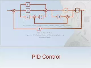
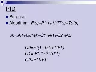
PID. (Proportional, Integral, Derivative) Control Systems. A presentation to the Robotics Society of Southern California May 11, 2013 By Alex Brown rbirac@cox.net. Introduction. PID is a method of controlling a dynamic system.

E N D
PID (Proportional, Integral, Derivative) Control Systems A presentation to the Robotics Society of Southern California May 11, 2013 By Alex Brown rbirac@cox.net
Introduction PID is a method of controlling a dynamic system. It consists of 3 simple calculations which are added together to generate a control signal to make your system track to a reference value. A tuned system gives the fastest response to an error. It doesn’t take a lot of math. Just testing to determine gains. It really only works well for simple linear systems; but its concepts can be applied to more complex systems.
Closed Loop Control System Control Signal Controller Process Reference E.g. motor, arm, temp, etc. E.g. PID Feedback
Control System for Robot Drive Motors PWM MOTOR PID Reference Forward Speed Feedback Tachometer or position encoder
Motor characteristics No Load “Normal” load Speed Heavy load Stall 100% PWM PWM No load with load Motor Speed Friction Inertia
P term (Proportional) PWM + Reference Forward Speed MOTOR Kp _ Feedback (Actual Speed) Bump 8 8 Speed Ref Speed Ref Step change 4 4 0 0 2 PWM PWM 1 0 8 Actual Speed Actual Speed 2 4 4 1 0 0 Hits bump
I term (Integral) Error PWM + + Reference Forward Speed MOTOR KP _ + KI Feedback (Actual Speed) 8 8 Turn integrator on here Speed Ref Speed Ref 4 4 0 0 Error 2 Error 2 0 0 Integrator Integrator PWM PWM Actual Speed Actual Speed 4 2 4 2 Hits bump
Integrator Windup Speed Ref 4 0 Kp Integ 300+ 50 PWM 100 50 Actual Speed 4 2
Integrator Windup (cont.) Rate KD _ PWM + Reference Forward Speed + MOTOR KP _ + KI Stop LOGIC Example logic: stop if total PWM is >= 100 and error is polarity to increase integrator. Stop if actual speed is converging with reference value stop if it is known that integrator will cause subsequent error.
D term (Derivative) KD Rate _ PWM + Reference Forward Speed + MOTOR KP _ + KI 8 Speed Ref Feedback (Actual Speed) 4 0 Error 2 0 Kp Rate PWM Actual Speed 4 2
PID PROs CONs Removes short term errors quickly Doesn’t remove long term errors Kp Has a fixed time constant Removes long term errors Removes errors very slowly. May cause integrator windup. KI Improves short term stability. Sometimes is NECESSARY depending on what is being controlled. KD PID Acts as above providing optimally fast response to errors Don’t have to use all the terms. We don’t always want optimally fast responses.
Is that all there is? In theory, a PID controller can succeed for any system that is linear. However, it may not perform just the way we would like. A pure PID system works best on a linear system with a slow moving reference or small reference changes. That’s no fun! We want our robots to respond quickly but smoothly to large changes of command. And our robot systems usually have many non-linearities. I worked on autopilot design for 30 years and never heard the word “PID” until I retired and started on robots. Our autopilots used one or more of the three PID terms at appropriate times usually with logic and/or other devices to achieve good performance in the real world.
Slow response to speed reference change As indicated earlier, a PI drive motor system will not quickly achieve the new reference speed until the integrator runs long enough to command the necessary additional PWM. We know that under normal conditions, there is a proportion between speed and PWM. Hence another term may be added (a “FeedForward” term) that approximates the PWM required at any commanded speed. This will usually provide much faster approach to the new reference and leave the integrator to only pick up any residual error . KFF Rate KP _ + PWM + Reference Forward Speed + MOTOR KP _ + KI
KP + KI +KFF KP Only KP + KI 8 Speed Reference 4 0 error 100 Integrator 40 0 100 KFF 40 0 100 PWM
Loops within Loops Outer loop Middle loop Servo loop or inner loop. PID PID PID Motor Motor feedback feedback Maneuvers vehicle smoothly. E.g speed and steering. Can be slower than servo loop. E.g. Navigation This may be the slowest response loop. Fastest loop. Moves motor/actuator to desired speed/position quickly.
Trapezoidal Speed Profile PID tracking Speed Reference Stopped Constant acceleration Constant speed Constant deceleration Stopped You can eliminate much of the PID tracking lag by adding an acceleration feed-forward term. Acceleration using this method works well. Deceleration is challenging due to the difficulty of determining when to begin slowing at a constant acceleration to stop at a target distance. My method is to continuously calculate the accel required to stop by the target distance. When that accel is >= desired deceleration, switch to controlling to the calculated accel and vary plus or minus to stop at target distance.
Application to real robots. Differential: MOTOR Reference Forward Speed PWM PID MOTOR Actual Speed Average PWM PID MOTOR Reference Forward Speed PWM PID MOTOR Both will work to hold forward speed, but both will have poor directional control with nothing to keep them in sync.
Need an upstream steering system like the below Reference Forward Speeds PWM PID MOTOR Reference Fwd Speed + Steering Left wheel PWM PID MOTOR Right wheel Or, a downstream “equalization” system as below MOTOR _ Reference Forward Speed + PWM PID _ + MOTOR Actual Speed Average But, it is still going to require steering someday.
Ackerman Steering forward speed control Reference Forward Speed PWM PID MOTOR Actual Speed Forward speed control is independent of steering
Or, as I prefer, an upstream steering system AND modifying the PID loop to control position (or distance) rather than speed. Reference Forward Distance PWM PID Common Reference Fwd Dist + Steering MOTOR Left wheel PWM PID MOTOR Right wheel Advantages: Simple PID loop. Only requires Kp. Very accurate dead reckoning of distance and steering. No integrator windup concerns. Minor distance offset will supply any PWM needed up to 100% Disadvantages: Requires feedback to Distance loop to ensure distance commands do not exceed motors ability to follow.
Reference Forward Distance Speed and Accel Left wheel AccelRef KFFacc _ + Common Reference Fwd Dist + Steering PWM + DistRef + MOTOR Kp + SpeedRef KFFspd Right wheel PWM MOTOR Same as above Maximum accel Reference accel Reference speed Reference distance Speed error Target fwd speed Accel limiter Generate Trapezoidal speed profile Calculate accel to stop at target distance Logic to begin decel
Steering Control We have two type of steering systems commonly used. Differential Drive Ackerman Steering
Steering Task Wall Following Target distance Target distance Measured distance Measured distance Error Error
Steering displacement +/- commands to L & R motor control loops Lateral Error + KP Steering displacement KD Rate _ Lateral Error + Angle command to steering servo KP
Steering displacement Lateral Error Limiter 45 deg + KP Error
KD Rate ? _ Lateral Error + KP Error
Conclusion Pure PID is best for inner loop where you want fast response. Even there just use the terms necessary to get the performance you want. Use the P, I & D terms freely in designing outer loop navigation when you want your control to converge on a steady reference exponentially. For more info on pure pid, google pid tutorials For more of my slant on it, try abrobotics.tripod.com. It includes a simulation program written by (ex) clubmember Lior Elazary.