Download
1 / 22
220 likes | 459 Views
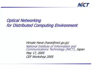
Optical Networking for Distributed Computing Environment. Hiroaki Harai (harai@nict.go.jp) National Institute of Information and Communications Technology (NICT), Japan May 17, 2005 CEF Workshop 2005. l. OXC. l. 1. 2. Research Background.

E N D
Optical Networking for Distributed Computing Environment Hiroaki Harai (harai@nict.go.jp) National Institute of Information and Communications Technology (NICT), Japan May 17, 2005 CEF Workshop 2005
l OXC l 1 2 Research Background • Distributed computing environment via Internet (GRID) • Difficult to assure delay and bandwidth • Best effort, TCP • Difficulty in tractability for application engineer • Distributed computing environment on wavelength-routed network (Optical GRID) • On request from an end host, a lightpath is established between two end hosts • Multi Gbit/s bandwidth is assured by directly connecting end host resources • Request may be blocked • Focus on Optical GRID CEF Workshop 2005 (H. Harai, NICT)
Research Goal and Contents • Contribute to advance in distributed computing technology and distributed computing application development by … • Using optical networking technology (optical component and control system) • Developing distributed computing environment that assures data transmission bandwidth between hosts • Develop distributed computing environment over l-path networks • 1st step: Dynamic establishment of optical ring (multiple paths connecting multiple computing sites) • Optical networking for distributed computing environment [today’s title] CEF Workshop 2005 (H. Harai, NICT)
Remaining Contents of This Talk • Make dynamic optical ring for distributed computing • Cooperating routing for point-to-point communications • Establishing an optical ring with minimal-cost by using a heuristic for traveling salesman problem • Mapping a ring composition to signaling • Evaluate performance • Apply ring composition concept to CEF network • Conclusion and future direction CEF Workshop 2005 (H. Harai, NICT)
Making Dynamic Optical Ring for Distributed Computing Environment
Image End-host Initial data l1 l3 Final computation result Wavelength-Routed Network OXC l2 Temporal Computational data Optical GRID environment Optical GRID <Image> • Develop distributed computing environment over WDM networks • Multi-site communications • High-speed channel (path) • guaranteed bandwidth CEF Workshop 2005 (H. Harai, NICT)
Optical Ring for Multi-Site Communications • Establishing a set of fully-meshed lightpaths is difficult • Tree or ring? • Light tree (bi-directional multicast tree) • Optimization: Find the least-cost tree by solving minimum Steiner tree problem • Required: Multicast capability at internal node • Optical ring (set of unidirectional lightpaths) • Optimization: Find the least-cost set of lightpaths by solving traveling salesman problem • Required: Data duplication at hosts • Making optical rings • Can reduce number of required wavelengths (channels) • Can use wavelength resources effectively CEF Workshop 2005 (H. Harai, NICT)
l1 l3 OXC l2 Making Optical Ring Dynamically • Make multiple lightpaths dynamically • Hosts establish an optical ring with … • Hosts receive routing information from network • Considering routing constraint (routing for point-to-point communication) • Each host decides a host closest to the host as a destination of a lightpath • Solving traveling salesman problem under limited route information of hosts • Each host establish a lightpath to the destination host • Map optical ring composition to wavelength reservation signaling CEF Workshop 2005 (H. Harai, NICT)
4 4 a a 5 5 b b 6 6 5 5 e e 2 2 1 1 c c 3 3 d d Considering Routing Constraint • It is practically difficult for nodes (routers) to have all the optimal routes for the unidirectional rings • For number of hosts N, the optimal number of routes for • Optical lightpaths (1to1) is N (N -1) • Optical rings (k-to-k) is • Optimal route for optical ring is different depending on number of hosts and set of hosts • Network does not exist only for multi-site communication • Nodes have point-to-point routing information only • Nodes advertise routing information to hosts • Each host has routing information from itself and does not have routing information that is not related to itself CEF Workshop 2005 (H. Harai, NICT)
1 2 4 a 5 b 6 e c d 3 4 a b e 2 c d 3 a 4 3 3 4 a a a a 5 b 5 5 6 b b b 6 b 5 e 2 5 5 5 e 2 e e e c 3 1 d 1 1 c c c 3 d 1 d d c 3 d Optical Ring Composition (TSP Heuristic) • [Parent] For set of hosts S={hs, h1, h2, …, hG-1}, Generate list of hosts assigned lightpath (L={ }), list of hosts not assigned lightpath (U= {hs,h1, h2, …, hG-1}) • [Parent] Remove hs from U, add it to L (L={hs}, U = {h1, h2, …, hG-1}). Establish a lightpath from hs to host h that is included in U and is the least-cost • [Child] Remove destination host h from list U and add it to list L (e.g., L={hs, hG-1}, U = {h1, h2, …, hG-2} if h=hG-1 ). If not U={ }, establish a lightpath from h to host that is included in U and is the least cost. Repeat this until U={ }. • [Child] Establish a lightpath from host that is included in list L most recently to host hs CEF Workshop 2005 (H. Harai, NICT)
Host (c) Host (b) a; L={a} U={b,c} Parent host (a) Parent host (a) a; L={a,b} U={c} a; L={a,b,c} U={ } RESERVE ACK P-ACK (ACK to parent) Data transfer Ring Composition to Wavelength Reservation Signaling (FORWARD direction) • If a lightpath is reserved • Destination host sends ACK to the source host • Destination starts reservation to the next lightpath • Source host sends P-ACK to the parent host • Otherwise, destination sends NACK to the source host • The parent host regards receiving all P-ACKs as success of ring establishment CEF Workshop 2005 (H. Harai, NICT)
Calculate average of total hop count for each number of hosts in a group Performance Evaluation (Number of Used Wavelengths) • Evaluate number of links required for communication in a group • 16-node (4x4 mesh) network • Tree: setting up bi-directional lightpaths from parent hosts to other hosts • Ring “Non-Shortest”: setting up unidirectional lightpaths in random order • Ring “Shortest”: setting up unidirectional lightpaths for optimal resource usage CEF Workshop 2005 (H. Harai, NICT)
Performance Evaluation (FORWARD) • Ring request: Poisson, holding time: exponential (mean 1) • G hosts in a group is selected randomly • At each source host, a wavelength is randomly selected for reservation • Larger G (G=10) slightly increases performance difference • Sustaining the number of links required gives good influences to the performance CEF Workshop 2005 (H. Harai, NICT)
Applying Ring Composition Conceptto Customer-Empowered-Fiber Network
Peer model is assumed in previous discussion End host is a unit of a network Collect routing information from the network Request a wavelength path Overlay model is possible in previous discussion End host estimates network topology in logical level End host estimates available wavelengths Estimate routing (virtual link cost) Signaling Routing Overlay model Peer Model, Overlay Model - Lightpath request - Estimate virtual topology and available wavelengths Peer model CEF Workshop 2005 (H. Harai, NICT)
Switch Connection Control Signaling Routing CEF Network Customer-Empowered-Fiber Network Model • End host can • Send control packets to the network (=peer model) • Obtain routing information (=peer model) • Set up internal connection of internal node ( peer model) • Communication between customer to every node • May consume time CEF Workshop 2005 (H. Harai, NICT)
Conclusion • Optical networking for distributed computing environment • Dynamic ring composition method for effective wavelength utilization • TSP heuristic • Signaling (FORWARD reservation) • Cooperation between nodes and hosts for lightpath establishment • Nodes only do routing for point-to-point communications and advertise the routing information to neighbor hosts • Hosts collect routing information and decide destination for lightpath establishment • Future direction • BACKWARD reservation (compatibility to GMPLS RSVP-TE) • Implementation • Deployment to Peer/CEF network CEF Workshop 2005 (H. Harai, NICT)
Tokyo JGN2 Future Direction (On Planning) • JGN2 (R&D testbed by NICT, http://www.jgn.nict.go.jp/e/) has 1/10Gbps L2/L3 lines, and dark fibers (G.655 NZDSF, G.652 SMF) NICT CEF Workshop 2005 (H. Harai, NICT)
Acknowledgment • Professor M. Murata (Osaka University) for valuable comments for optical networking • Dr. F. Kubota, and Dr. T. Miyazaki (NICT) for experiment planning discussion CEF Workshop 2005 (H. Harai, NICT)