Download
1 / 21
210 likes | 333 Views
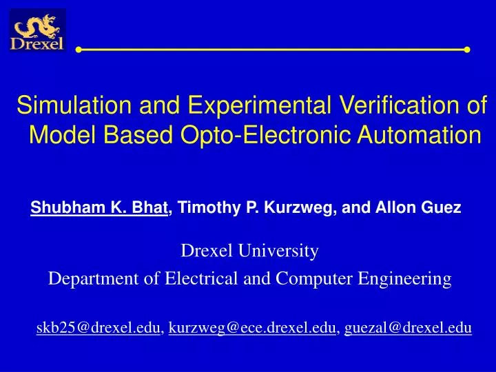
Simulation and Experimental Verification of Model Based Opto-Electronic Automation. Shubham K. Bhat , Timothy P. Kurzweg, and Allon Guez. Drexel University Department of Electrical and Computer Engineering. skb25@drexel.edu , kurzweg@ece.drexel.edu , guezal@drexel.edu. Overview.

E N D
Simulation and Experimental Verification of Model Based Opto-Electronic Automation Shubham K. Bhat, Timothy P. Kurzweg, and Allon Guez Drexel University Department of Electrical and Computer Engineering skb25@drexel.edu, kurzweg@ece.drexel.edu, guezal@drexel.edu
Overview • Motivation • Current State-of-the-Art Photonic Automation • Our Technique: Model Based Control • Optical Modeling Techniques • Learning Model Identification Technique • Conclusion and Future Work
Motivation Automation is the key to high volume, low cost, and high consistency manufacturing ensuring performance, reliability, and quality. • No standard for OE packaging and assembly automation. • Misalignment between optical and geometric axes • Packaging is critical to success or failure of optical microsystems • 60-80 % cost is in packaging
Stop Stop Current State-of-the-Art “Hill-Climbing” Technique Assembly Alignment Task Parameters Visual Inspect and Manual Alignment ApproximateSet Point=Xo Initialization Loop Move to set point (Xo) Measure Power (Po) • LIMITATIONS: • Multi-modal Functions • Multi-Axes convergence • Slow, expensive Off the shelf Motion Control (PID) (Servo Loop) Stop motion Fix Alignment
Model Based Control Correction to Model Parameter Learning Algorithm Model Parameter Adjustment FEED - FORWARD Set Point=Xo Visual Inspect and Manual Alignment Assembly Alignment Task Parameters Optical Power Propagation Model {Xk}, {Pk} Initialization Loop Move to set point (Xo) Measure Power (Po) • ADVANTAGES: • Support for Multi-modal Functions • Technique is fast • Cost-efficient Off the shelf Motion Control (PID) (Servo Loop) Stop motion Fix Alignment
R(s) Pr(s) Pd(s) Kp E(s) + + + - Kp If = P, Model Based Control Theory
Optical Modeling Technique • Use the Rayleigh-Sommerfeld Formulation to find a Power Distribution model at attachment point • Solve using Angular Spectrum Technique • Accurate for optical Microsystems • Efficient for on-line computation Spatial Domain Spatial Domain Fourier Domain
Inverse Model • For Model Based control, we require an accurate inverse model of the power • However, most transfer functions are not invertible • Zeros at the right half plane • Unstable systems • Excess of poles over zeros of P • Power distribution is non- monotonic (no 1-1 mapping) • Find “equivalent” set of monotonic functions
Inverse Model: Our Approach • Decompose complex waveform into Piece-Wise Linear (PWL) Segments • Each segment valid in specified region • Find an inverse model for each segment
Need for Learning Model • The structure of the system and all of its • parameter values are often not available. • Noise, an external disturbance, or inaccurate • modeling could lead to deviation from the actual • values. • Adjust the accuracy on the basis of experience. Real System Input Output + Adjustment Scheme Error - Estimated model Model
Learning Model IdentificationAlgorithm Step 1: Assume system to be described as , where y is the output, u is the input and is the vector of all unknown parameters. Step 2: A mathematical model with the same form, with different parameter values , is used as a learning model such that Step 3: The output error vector, e , is defined as Step 4: Manipulate such that the output is equal to zero. Step 5: It follows that and
Learning Model Identification Technique Real System Input Output + Estimated model of unknown parameters Output Error - Model Sensitivity equations
Learning Model Identification example We present a two unknown system having input-output differential equation ( a and K are unknown ) The variables u, y, and are to be measured { } Step 1: and Step 2: { Assume estimated model and } Step 3: The Sensitivity coefficients are contained in where , and
Learning Loop of PWL Segment . Input Power + Displacement - (P) (u) (x) K For each PWL Segment: L-1
: Updated Model Learning for 2 Unknown Variables (PWL Segment) S: Sensitivity matrix • a and K have initial estimates of 0.1 and 4 • Actual values of a and K are 1.44 and 5.23 e: error matrix Q: weighting matrix e: tracking parameter
Example: Laser Diode Coupling Aperture = 20um x 20um Fiber Core = 4 um Prop. Distance = 10 um Edge Emitting Laser Coupled To a Fiber Distance = 10um No. of. Peaks = 10 NEAR FIELD COUPLING
1.5 1.3 1.1 20 0.9 18 0.7 16 14 12 Model Based Control System Fiber Position (12.6 um) Inverse Model Received Power + Derivative (1.41 ) + Nominal Model Desired Power Proportional Gain + + K (1.41) - Motor Dynamics Plant Model 1.5 1 K 0.5 Proportional Gain Time Taken = 7 seconds 0
Test bed for Verification X-Y Stage Laser Diode Driver Optical Power Sensor Optical Source Motion Control Card X Amplifier Y Amplifier Pre-amplifiers, encoders We acknowledge Kulicke and Soffa, Inc. for the donation of the XY Table
Test bed for Verification Optical Power Sensor Laser Diode Driver X-Y Stage
Conclusions and Future Work • Model based control leads to better system performance • Inverse model determined with PWL segments • Learning loop can increase accuracy of model • Shown increased performance in simulated systems • Hardware implementation • Evaluate other learning techniques • Error prediction in models