Download
1 / 29
290 likes | 292 Views
Task 2.1: proposal for test conditions of MAC efficiency Simulation of “Seasonal Performance” of MAC system to determine most important ambient conditions Analysis of Weather Data Simulations by means of “Seasonal Performance” (LCCP). Seasonal Performance. based on Green MAC LCCP

E N D
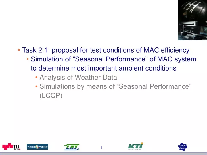
Task 2.1: proposal for test conditions of MAC efficiency • Simulation of “Seasonal Performance” of MAC system to determine most important ambient conditions • Analysis of Weather Data • Simulations by means of “Seasonal Performance” (LCCP)
Seasonal Performance • based on Green MAC LCCP • aim: evaluation of different factors influencing MAC fuel consumption
0.1 0.18 0.09 daily usage 0.16 0.08 0.14 0.07 0.12 0.06 0.1 0.05 proportion 0.04 proportion 0.08 0.03 0.06 0.02 0.04 0.01 0.02 weekly usage 0 0 0 4 8 12 16 20 24 Mo Di Mi Do Fr Sa So Hours Seasonal Performance(based on GM LCCP) weather data • Meteonorm 6.0 • average weather data from Europe for every hour of the year -> different than in GM LCCP driving cycle & costumer usage NEDC costumer usage according to Pinkofsky (2006)
Capacity & COP Seasonal Performance(based on GM LCCP) MAC technology Data for Capacity and COP: Baseline system from GM LCCP used within this studies „enhanced“ system from SAE ARCRP_2002: variable displacement compressor, condenser with integrated receiver, TXV, no IHX (like System B) engine/vehicle data According to GM LCCP „incremental engine efficiency“ (40% for Gasoline and 45% for Diesel engines)
Which are the most important ambient conditions concerning the real operation of the MAC system? • investigation of three „typical“ climates • hot: Athens • medium: Frankfurt • cold: Helsinki
Weather, e.g. Athens % AC fuel consumption of annual AC fuel consumption depending on ambient temperature i.e. 7.5% of the annual fuel consumption of the ac system is caused at ambient temperatures of 30°C (in Athens) => proposal for test condition #1: 30°C/40%* i.e. ≈ 58 kJ/kg *average relative humidity at 30°C (700 W/m2 or equivalent)
Weather, e.g. Frankfurt % AC fuel consumption of annual AC fuel consumption depending on ambient temperature => proposal for test condition #2: 21°C/62%* or 20°C/65% i.e. ≈ 45 kJ/kg *average relative humidity at 21°C (500 W/m2 or equivalent)
Weather, e.g. Helsinki % AC fuel consumption of annual AC fuel consumption depending on ambient temperature => proposal for test condition #3: 15°C/75%* i.e. ≈ 35 kJ/kg *average relative humidity at 15°C (300 W/m2 or equivalent)
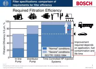
Proposal for test conditions • 15°C/75% i.e. ≈ 35 kJ/kg (300 W/m2) • 20°C/65% i.e. ≈ 45 kJ/kg (500 W/m2) • 30°C/40% i.e. ≈ 58 kJ/kg (700 W/m2) • Remark (results from simulation of refrigerant cycle): • 1 K at inlet temperature will result in a variation of ≈ 5% to 10% in cooling capacity (greater impact at lower ambient temp.) • 3 % at inlet humidity will result in a variation of ≈ 5% in cooling capacity -> important for control of climatic chamber!
Task 2.2: proposal for procedures for testing MAC performance at type approval • Investigation of different factors influencing the MAC fuel consumption • solar load • refrigerant cycle technology • recirculation air (in idle mode) • engine • driving conditions • proposal for test procedure
MAC Efficiency SAE IMAC (B. Hill, VDA Wintermeeting, 2006) • Reduction of solar load by 30% seems to be realistic (e.g. by special glazing) • Improvement of COP by 30% over baseline system (i.e. enhanced R134a system of the ARCRP) seems to be realistic (especially at part load conditions)
no solar load with solar load reduction of solar load by 30% Solar Load Estimation of influence of solar irradiation on annual MAC fuel consumption 1,8 1,6 remark: - fuel consumption is referred to “no solar load” for each city - for sure fuel consumption of Helsinki differs from Athens 1,4 1,2 1,0 rel. fuel consumption of MAC 0,8 0,6 0,4 0,2 0,0 Helsinki Frankfurt Athens • solar irradiation causes approx. 25 to 50% additional fuel consumption • fuel consumption can be reduced by approx. 5 to 15% if solar load is reduced by 30%
MAC Technology • COP of refrigerant cycle improved by 15% at full load conditions and 30% for part load conditions => improvement of approx. 20%
Idle (Recirculating Air in Front End) • Assumption: no COP reduction by recirculating air in front end => improvement > 10%
Engine • in GM LCCP (and therefore in Seasonal performance simulations) an “incremental engine efficiency” is defined • incremental efficiency is independent from rpm and engine size Diesel vs. Gasoline • “incremental engine efficiency”: 45% for Diesel and 40% for Gasoline Gasoline 1 vs. Gasoline 2 (and Diesel 1 vs. Diesel 2): • MAC system causes the same additional fuel consumption (absolute) for different engines of same type (in the same vehicle) -> is this a realistic assumption (within the field of this project)??? -> open issue?! -> to be investigated within the measurements?!
Engine • R134a Baseline System: Diesel vs. Gasoline => difference of approx. 8%
Intermediate Summary • MAC system shows “room for improvement” concerning • reduction of solar load • COP of refrigerant cycle • idling seems to play a very important role -> impacts should be considered within test procedure • open issues: • test procedure (driving conditions) • choice of vehicles • repeatability of measurements
Driving Conditions % AC fuel consumption of AC fuel consumption (based on NEDC driving) in dependency from Compressor Speed proposal for measurements: idle and 3000 rpm
Test Procedure - Proposal • electrical heater in vehicle • to represent solar load: solar load to be calculated by means of simulation (e.g. tool like VSOLE from NREL) for each car individually (requires tests to verify tool) • no pre-soaking of vehicle cabin (i.e. t_cabin = t_ambient) • high effort (time for soaking) • repeatability might be poor (e.g. caused by different temperature distribution, i.e. soaking equipment & procedure) • Steady State Driving with 2 phases: 65 km/h & Idle • for phase 1 (driving): blower in front of vehicle • for phase 2 (idling): blower off -> recirculating air will be considered • set point: 21°C*, mode: “auto” -> control will be consideredor “manual” with fresh air (probably better repeatability) • warm start (t > x°C) *according to DIN1946-3
Subjects of the service request to be covered by the measurement campaign • Provide data for impact assessment of MAC and GSI regulations • Developing test conditions and procedures for MAC and GSI efficiencya) simulation + chassis dyno tests b) simulation +MAC test stand Influence of: different ambient conditions different test cycles and test procedures different engine types (gasoline, diesel, swept volume,..) different vehicle specifications (color, glassing,…) different MAC technologies Repeatability, reproducibility, sensitivity Possible metrics for MAC efficiency (g/km, g/h, kJ/(kg °K),…) test procedure type approval families
Measurement plan Tasks for MAC tests M-1.1) Parameterization and validation of the simulation of the sun radiation -> Park vehicles outside in sun (LAT, JRC) Instantaneous measurement: *sun radiation intensity, *parking time*tinterior (10cm below vehicle roof above driver seat)+vehicle data, glass material Result -> heat input (% from radiation or w/m²)
Measurement plan Tasks for MAC tests M-1.2) Influence of MAC in real world driving (if JRC is interested in performing such tests) -> Measure with PEMS after vehicles parked outside in sun (JRC) chasing of 2 similar vehicles, one MAC off, the other MAC on Instantaneous measurement: *parking as 1)* tinterior*CO2 (g/km) + other emissions *velocity*engine speed (and torque if possible)*road gradient (if not flat road) Result -> additional gCO2/km from MAC if repeated (incl. parking) at different ambient conditions: additional g CO2/km as function of ta and humidity
Measurement plan Tasks for MAC tests M-2) Test options at the chassis dynamometer -> Measure different cycles at different temperature and humidity levels in the test cell. Effect of sun radiation depictured with heat flow from electrical heater inside of vehicle. Instantaneous measurement: * tinterior* tveh.intake & humidity (position before heat exchanger of MAC)*CO2 (g/km) + other emissions *velocity, braking force at rollers*engine speed (and torque if possible) Cycles: NEDC (cold start and hot start), CADC, MAC-STEP, at 3 different t/humidity combinations (Helsinki, Frankfurt, Athens), 2 different MAC-settings (21°C and 24°C) heat flow in vehicle for W/m² in corresponding city
MAC-Step test cycle Measurement plan 2 engine loads, long duration -> good repeatability? + sensitivity 0/50/100 km/h
Test cycles NEDC CADC HBEFA
Measurement plan Proposed Test Matrix per vehicle Sensitivity tests Capabilities of labs:For MAC testing: conditioning of test bed for defined t and humidity within very narrow ranges (h=Dcp*Dt ~ +/- 1kJ/kg)!! Alternative: develop method for correction of t and humidity influences
Measurement plan Time schedule 15.3. Selection and test of heater 30.3. Start tests at TUG 30.4. Start tests at KTI 30.4. Start tests at LAT 30.5. Finalization of all test runs ?? Tests at the MAC test stand (as alternative for chassis dyno TA?) 13.8. Project end Validation at JRC ??after project end (e.g. only finally suggested test + NEDC)or test also during project (full or part of test matrix)?
Measurement plan Proposed Gear shift points Gear shift points* average as defined in cycle (NEDC, CADC)* average for HBEFA to be simulated for specific vehicle (TUG)* ECO-, aggressive style simulated by PHEM (test first at TUG)* GSI: follow GSI suggestion from vehicle Proposed Test vehicles TUG+KTI: BMW 318d (efficient dynamics) from TUG -> reproducibility and repeatability (budget for vehicle rent and electric heater at KTI?) LAT: BMW 318i -> influence of engine or BMW 118d -> influence of vehicle size or other make and model: influence of everything (maybe class E MAC category?) to be defined after tests at TUG JRC: variations of engine, MAC-system, vehicle size,… (depend on LAT selection)