Download
1 / 36
360 likes | 472 Views
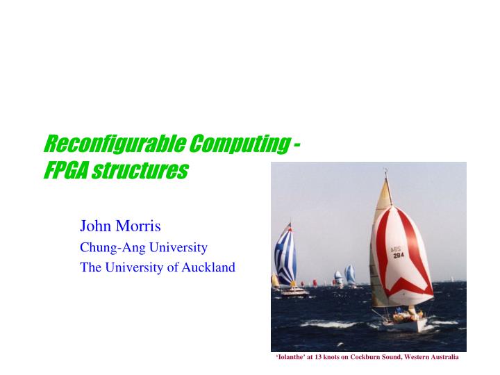
Reconfigurable Computing - FPGA structures. John Morris Chung-Ang University The University of Auckland. ‘Iolanthe’ at 13 knots on Cockburn Sound, Western Australia. FPGA Architectures. Programmable logic takes many forms Originally devices contained 10’s of gates and flip-flops

E N D
Reconfigurable Computing -FPGA structures John Morris Chung-Ang University The University of Auckland ‘Iolanthe’ at 13 knots on Cockburn Sound, Western Australia
FPGA Architectures • Programmable logic takes many forms • Originally devices contained 10’s of gates and flip-flops • These early devices were generally called PAL’s (Programmable Array Logic) • A typical structure was • With 10-20 inputs and outputs and ~20 flip-flops,they could • implement small state machines and • replace large amounts of discrete ‘glue’ logic FF ProgrammableAnd-Or array FF FF Inputs (20) Outputs (20) FF
Programmable Logic • Memory should also be included in the class of programmable logic! • It finds application in LUTs, state machines, ... • From early UV EPROMs with ~kbytes,we now have many styles of memory which retains values when power is removedand capacities in Mbytes Memory is an important consideration when designing reconfigurable systems. FPGA technology does not provide large amounts of memory and this can be a constraint - especially if you are trying to produce a compact,single chip solution to your problem!
Modern Programmable Logic • As technology has evolved, so have programmable devices • Today’s FPGAs contain • Millions of ‘gates’ • Memory • Support for several I/O protocols - TTL, LVDS, GTL, … • Arithmetic units - adders, multipliers • Processor cores
FPGA Architecture • The ‘core’ architecture of most modern FPGAs consists of • Logic blocks • Interconnection resources • I/O blocks
Typical FPGA Architecture • Logic blocksembedded in a‘sea’ of connectionresources • CLB = logic blockIOB = I/O bufferPSM = programmable switch matrix This particular arrangement is similar to that in Xilinx 4000 (and onwards) chips - devices from other manufacturersare similar in overall structure
Typical FPGA Architecture • Logic blocks embedded in a ‘sea’ of connectionresources • CLB = logic blockIOB = I/O bufferPSM = programmable switch matrix • Interconnections critical • Transmission gates on paths • Flexibility • Connect any LB to any other • but • Much slower than connections within a logic block • Much slower than long lines on an ASIC • Aside: • This is a ‘universal’ problem - not restricted to FPGAs! • Applies to • • custom VLSI, • • ASICs, • • systems, • • parallel processors • Small transistors high speed high density long, wide datapaths
Logic Blocks • Combination of • And-or arrayorLook-Up-Table (LUT) • Flip-flops • Multiplexors • General aim • Arbitrary boolean function of several variables • Storage • Designers try to estimatewhat combination of resourceswill produce the most efficientapplication circuit mappings • Xilinx 4000 (and on) CLB • 3 LUT blocks • 2 Flip-Flops (Asynch Reset) • Multiplexors • Clock / Reset Lines
Adders • Adders appear in most designs • Arithmetic Adders (including subtracters) • Other arithmetic operators • eg multipliers, dividers • Counters (including program counters in processors) • Incrementors, decrementors, etc • They also often appear on the critical path • Adder performance can be crucial for system performance • Because of their importance, researchers are still searching for better ways to add! • Adder structures proposed already • Ripple carry • Carry select • Carry skip • Carry look-ahead • Manchester • … and several dozen more variants
an-1 a1 bn-1 b1 an-2 a0 bn-2 b0 FA FA FA FA cout cout cin cin cout cout cin cin sn-1 s1 sn-2 s0 carryout Ripple Carry Adder • The simplest and most well known adder • How long does it take an n-bit adder to produce a result? • n x propagation delay( FA: (a or b) carry ) • We can do better than this - using one of many known better structures • but • What are the advantages of a ripple carry adder? • Small • Regular • Fits easily into a 2-D layout! Very important in packing circuitry into fixed 2-D layout of an FPGA!
an-1 a3 a1 bn-1 b1 b3 an-2 a2 a0 bn-2 b2 b0 FA FA FA FA FA FA cout cout cout cin cin cin cout cout cout cin cin cin sn-1 s1 s3 sn-2 s0 s2 carryout LB LB LB On an FPGA,this link is often the major source of time delay … because one or two FA blocks will often fitin a logic block! Ripple Carry Adders • Ripple carry adder performance is limited by propagation of carries Connections within a logic block are fast! Connections between logic blocks are slower
Using general interconnect Every one of these connection points is a transmission gate • Interconnections critical • Transmission gates on paths • Flexibility • Connect any LB to any other • but • Much slower than connections within a logic block • Much slower than long lines on an ASIC This switch matrix isa mass of transmission gates too!
‘Fast Carry’ Logic • Critical delay • Transmission of carry out from one logic block to the next • Solution (most modern FPGAs) • ‘Fast carry’ logic • Special paths between logic blocks used specifically for carry out • Very fast ripple carry adders! • More sophisticated adders? • Carry select • Uses ripple carry blocks - so can use fast carry logic • Should be faster for wide datapaths? • Carry lookahead • Uses large amounts of logic and multiple logic blocks • Hard to make it faster for small adders!
Logic Blocks and fast carry Direct connections to CLB above (in the same column) Cout Cindown • Xilinx solution • Carry logicprecedes LUTs • Fast carryconnections • Up • Down • Adders must lie in a column of the FPGA • Some(not serious?) constraint on layout G carry G1-4 F carry F1-4 Note that carry chains canrun either up or down (But not sideways!) Cinup Cout Direct connections to CLB below (in the same column)
Logic Blocks and fast carry - Altera version • Altera • Simpler logic element • One LUT and one flip-flop / logic element • Four inputs + one output / logic element • Simpler LE more LEs / device • Carry logic follows LUT • Carry chains in one direction only • Additional fast link (cascade chain) • Efficient implementation of high fan-in functions • eg 4+-input gate spans 2+ LEs with a slow link • Cascade chain avoids the slow link • Efficient (fast) high fan-in functions • eg Potentially much faster carry look-ahead adder? • Discussed later! • Is Xilinx better? • It’s unlikely to be superior for all applications!!
Carry Select Adder a4-7 b4-7 0 cin a0-3 cout7 b0-3 n-bit Ripple Carry Adder sum04-7 cout3 n-bit Ripple Carry Adder 1 b4-7 cout7 n-bit Ripple Carry Adder sum0-3 sum14-7 ‘Standard’ n-bit ripple carry adders n = any suitable value 0 1 0 1 Here we build an 8-bit adder from 4-bit blocks carry sum4-7
These two blocks ‘speculate’ on the value of cout3 This block adds the 4 low order bits After 4*tpd it will produce a carry out Carry Select Adder a4-7 b4-7 0 cin a0-3 cout7 b0-3 n-bit Ripple Carry Adder sum04-7 cout3 n-bit Ripple Carry Adder 1 b4-7 cout7 n-bit Ripple Carry Adder sum0-3 sum14-7 One assumes it will be 0 the other assumes 1 0 1 0 1 carry sum4-7
This block adds the 4 low order bits After 4*tpd it will produce a carry out Carry Select Adder • After 4*tpd we will have: • sum0-3 (final sum bits) • cout3 (from low order block) • sum04-7 • cout07 (from block assuming 0 cin) • sum14-7 • cout17 (from block assuming 1 cin) a4-7 b4-7 0 cin a0-3 cout7 b0-3 n-bit Ripple Carry Adder sum04-7 cout3 n-bit Ripple Carry Adder 1 b4-7 cout7 n-bit Ripple Carry Adder sum0-3 sum14-7 0 1 0 1 carry sum4-7
Carry Select Adder a4-7 b4-7 0 cin a0-3 cout7 b0-3 n-bit Ripple Carry Adder Cout3 selects correct sum4-7 and carry out sum04-7 cout3 n-bit Ripple Carry Adder 1 b4-7 cout7 n-bit Ripple Carry Adder sum0-3 sum14-7 0 1 0 1 All 8 bits + carry are available after 4*tpd(FA) + tpd(multiplexor) carry sum4-7
Each ripple carry block should use fast carry logic Carry Select Adder a4-7 b4-7 0 cin a0-3 cout7 b0-3 n-bit Ripple Carry Adder sum04-7 cout3 n-bit Ripple Carry Adder 1 b4-7 cout7 n-bit Ripple Carry Adder sum0-3 sum14-7 0 1 0 1 Drawback: These links are relatively slow! CSA only faster for n > ? carry sum4-7
Carry Select Adder • This scheme can be generalized to any number of bits • Select a suitable block size (eg 4, 8) • Replicate all blocks except the first • One with cin = 0 • One with cin = 1 • Use final cout from preceding block to select correct set of outputs for current block
Better adders • Performance of a CSA is still O(n) • More sophisticated adders? • Carry skip • Variant on carry select idea • Carry lookahead • Uses large amounts of logic and multiple logic blocks • Hard to make it faster for small adders!
Carry Lookahead Adder • Standard adder expressions • cout = a•b + b•cin + a•cin • sum = a bcin • Define two new symbols • ‘Generate’ G= a•b • If a and b are both 1, then a carry must be generated • ‘Propagate’ P = a b • If ab (a b = 1), then propagate the carry in • Now • sum = Pcin • cout = G + cinP • For theithbit • sumi = Pici • ci+1 = Gi + ciPi
Carry Lookahead Adder • Expanding the carry expressions • c1= G0 + c0P0 • c2= G1 + c1P1= G1 + P1 (G0 + c0P0) = G1 + P1G0 + c0P1P0 • c3= G2 + c2P2= G2 + P2(G1 + c1P1) = G2 + P2(G1 + P1( G0 + c0P0)) = G2 + P2G1 + P2P1G0 + c0P2P1P0 • c4= G3 + c3P3= G3 + P3(G2 + c2P2) = ... = G3 + P3G2 + P3P2G1 + P3P2P1G0 + c0P3P2P1P0 • Note that c4 can be calculated in a logic block that permits • 4 P inputs • 4 G inputs • c0 input • Fortuitously, this is exactly what a Xilinx CLB allows! • This may be an accidental coincidence! • An Altera LE can use cascade in to calculate c4 using several LEs without serious propagation delay penalty
Large Carry Lookahead Adders • Define ‘group’ generate and propagate symbols • For 4-bit ‘groups’ • PG= P3P2P1P0 • GG= G3 + P3G2 + P3P2G1 + P3P2P1G0 • c5= G4 + c4P4= G4 + P4(G3 + c3P3) = ... = G4 + P4G3 + P4P3G2 + P4P3P2G1 + P4P3P2P1G0+ c0P4P3P2P1P0= G4 + P4(GG + PGc0) • Note that the expression for c5 has exactly the same form as the expression for c1 - substituting (GG + PGc0) for c0 • Thus large CLAs are built by cascading blocks that compute group G and P signals
b4-7 b0-3 a4-7 a0-3 c8 c4 PG s8-11 GG PG s4-7 PG s0-3 GG GG c1 G2 P2 c2 G1 P1 Cascading blocks for large CLAs b16-19 b12-15 b8-11 a16-19 a12-15 a8-11 c12 PG s16-19 PG s12-15 GG GG G0 P0 c0 G3 P3 c3 G0 P0 c0 PG PG GG GG G0 G1 P1 c1 P0 PG GG 4-bit adder blockmodified to calculate G and P
Large Carry Lookahead Adders • Define ‘group’ generate and propagate symbols • Thus large CLAs are built by cascading blocks that compute group G and P signals • As with CS Adders, optimum group size will be determined by the technology used • It will need to match logic block capability • It will need to balance internal LUT propagation delay with link delay • effectiveness of additional capabilities, eg Altera cascade chains • Some experimentation will be needed to determine it! • CLA overheads are high • Unlikely to be effective for small adders! • Some experiments we have done suggest >64 bits needed!
Fast Adders • Many other fast adder schemes have been proposedeg • Carry-skip • Manchester • Carry-save • Carry Look Ahead • If implementing an adder (eg in programmable logic) • do a little research first!
Fast Adders • Challenge: What style of adder is fastest / most compact for any FPGA technology? • Answer is not simple • For small adders (n < ?), fast carry logic will certainly make a simple ripple carry adder fastest • It will also use the minimum resources - but will need to be laid out as a column or row • For larger adders ( ? < n < ? ), carry select styles are likely to be best - • They use ripple carry blocks efficiently • For very large adders ( n > ? ), a carry look ahead adder may be faster? • But it will use considerably more resources!
Exploiting a manufacturer’s fast carry logic • To use the Altera fast carry logic, write your adder like this: LIBRARY ieee; USE ieee.std_logic_1164.all; LIBRARY lpm ; USE lpm.lpm_components.all ; ENTITY adder IS PORT ( c_in : IN STD_LOGIC ; a, b : IN STD_LOGIC_VECTOR(15 DOWNTO 0) ; sum : OUT STD_LOGIC_VECTOR(15 DOWNTO 0) ; c_out : OUT STD_LOGIC ) ; END adderlpm ; ARCHITECTURE lpm_structure OF adder IS BEGIN instance: lpm_add_sub GENERIC MAP (LPM_WIDTH => 16) PORT MAP ( cin => Cin, dataa => a, datab => b, result => sum, cout => c_out ) ; END lpm_structure ;
What about that carry in? • In an ALU, we usually need to do more than just add! • Subtractions are common also • Observe • c = a - b is equivalent to • c = a + (-b) • So we can use an adder for subtractions if we can negate the 2nd operand • Negation in 2’s complement arithmetic?
Adder / Subtractor • Negation in 2’s complement arithmetic? • Rule: • Complement each bit • Add 1 • eg Binary Decimal 0001 1 Complement 1110 Add 1 1111 -1 0110 6 Complement 1001 Add 1 1010 -6
FA FA Adder / Subtractor • Using an adder • Complement each bit using an inverter • Use the carry in to add 1! a b 0 1 add/ subtract cin FA carry c
Example - Generate ENTITY adder IS GENERIC ( n : INTEGER := 16 ) ; PORT ( c_in : IN std_ulogic ; a, b : IN std_ulogic_vector(n-1 DOWNTO 0) ; sum : OUT std_ulogic_vector(n-1 DOWNTO 0) ; c_out : OUT std_ulogic ) ; END adder; ARCHITECTURE rc_structure OF adder IS SIGNAL c : STD_LOGIC_VECTOR(1 TO n-1) ; COMPONENT fulladd PORT ( c_in, x, y : IN std_ulogic ; s, c_out : OUT std_ulogic ) ; END COMPONENT ; BEGIN FA_0: fulladd PORT MAP ( c_in=>c_in, x=>a(0), y=>b(0), s=>sum(0), c_out=>c(1) ) ; G_1: FOR i IN 1 TO n-2 GENERATE FA_i: fulladd PORT MAP ( c(i), a(i), b(i), sum(i), c(i+1) ) ; END GENERATE ; FA_n: fulladd PORT MAP (C(n-1),A(n-1),B(n-1),Sum(n-1),Cout) ; END rc_structure ;
Serial Circuits • Space efficient • Sloooow • One bit of result produced per cycle • Sometimes this isn’t a problem • Highly parallel problems • Search • Many operations on the same data stream • eg search a text database for many keywords in parallel =key0? Serial processing needs: 8xMbits/s - Easy! =keyi? Text stream =keyi? =keyi? Effective performance may require comparison with 1000’s of keys space for key circuits critical! small, compact bit-serial comparator ideal! Data rate: xMB/s =keyn?
Serial Circuits sum a 2-bit register • Bit serial adder FA b cout cin ENTITY serial_add IS PORT( a, b, clk : IN std_logic; sum, cout : OUT std_logic ); END ENTITY serial_add; ARCHITECTURE df OF serial_add IS SIGNAL cint : std_logic; BEGIN PROCESS( clk ) BEGIN IF clk’EVENT AND clk = ‘1’ THEN sum <= a XOR b XOR cint; cint <= (a AND b) OR (b AND cint) OR (a AND cint ); END IF; END PROCESS; cout <= cint;END ARCHITECTURE df; clock Note: The synthesizer will insert the latch on the internal signals! It will recognize the IF clk’EVENT … pattern!