Download
1 / 48
480 likes | 642 Views
Reconfigurable Computing Applications. Ed Carlisle. Outline. Reconfigurable Multi-Core Platform E-health and robotics case s tudies Reconfigurable Computing Framework for Robotics

E N D
Reconfigurable Computing Applications Ed Carlisle
Outline • Reconfigurable Multi-Core Platform • E-health and robotics case studies • Reconfigurable Computing Framework for Robotics • Leverages dynamic partial reconfiguration to fully utilize smaller devices required from tight constraints of micro UAVs • SURF Image Processing on Xilinx Zynq SOC • Tremendous speedup achieved over software SURF implementation • Conclusions
Dennis Majoe, Lars Widmer, Liu Ling, Jim Chih-Chen Kao, JürgGutknecht 2012 IEEE/ACIS 11th International Conference on Computer and Information Science A reconfigurable multi-core computing platform for robotics and e-health applications
RC System Development • Reconfiguration can be useful both during development for debugging and after development for functional upgrades • Typically algorithms are mapped to a custom architecture to be implemented on an FPGA • High development costs for register transfer level (RTL) • General purpose soft-cores can be used to increase efficiency of development • Xilinx’s MicroBlaze and Altera’s Nios II cores • Can even be used to run Linux operating system • May limit amount of parallelism that can be exploited
E-Health Case Study • Group relaxation session with 5 patients • Each patient uses an EEG sensor to determine their level of relaxation and compare with rest of the group • Parallel FFT analysis is performed on each EEG stream • Processing and visualization must happen simultaneously in real time
Robotics Case Study • Must process 60 sensor signals and produce 30 output control signals • 7 moving limbs • 4 or more actuators each • Each limb contains accelerometers, angle and pressure sensors • Machine learning is used to stabilize and maneuver the robot • Data processing must occur in real time
System Architecture • Virtex 5XC5VLX50T FPGA • Tiny Register Machine (TRM) • 2 stage pipeline running at 116MHz • Very light on FPGA resource usage • Communication between cores buffered with FIFOs • RF sensor communication over SPI protocol • Application software written in OBERON • Development environment integrated into Xilinx ISE • Software is instantiated onto parallel TRM cores • Software can be targeted at a specific core or generalized for a group of parallel cores
EEG Data Stream Processing • Data_Center provides SPI communication to RF sensors for data input from EEGs • FFT_Cells perform 512 point floating-point FFT calculations • Final_TRM_Cell groups results and prepares data for transfer over RF to output display
Robot Hierarchical Processing • Machine learning handled by Clustering and State Classification Cells • Clustering Cell performs feature extraction • Wireless IO Cell used for communications with RF components • Data Center Cell is responsible for formatting data for use with processing cells
Platform Development Results • Communication between FPGA prototype and robot I/O processors was verified • Machine learning, goal direction, and classification processing cells are still under construction • SPI communication with RF sensors has been measured at 120KB/s per channel • Internal communication between processing cells achieved 100MB/s with latency between 10-50 ns • 512 point floating-point FFT for EEG processing completes in 9.52 ms at 100MHz clock rate
MoazzamHussain, Ahmad Din, Massimo Violante, BasilioBona 2011 IEEE/ASME International Conference on Advanced Intelligent Mechatronics An Adaptively Reconfigurable Computing Framework for Intelligent Robotics
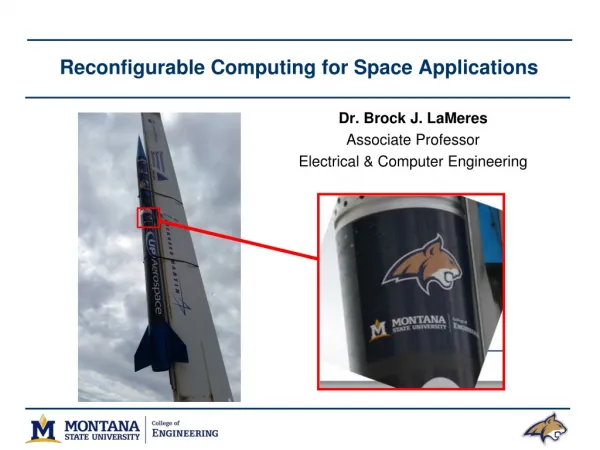
Introduction • Micro Unmanned Aerial Vehicles (UAVs) are designed to be easily transportable platforms for rapid deployment with very small payloads • Ground Control Stations (GCS) are used after deployment to control and acquire information from micro UAVs • Post-disaster assessment case study will be explored • Micro UAVs provide affordable and timely access to imagery of affected areas
Micro UAV System Constraints • Micro UAVs have tight constraints for processing payload size and power consumption • Dynamic Reconfiguration can allow the use of smaller FPGA devices by reusing the same region for multiple tasks • Onboard computers usually work in a controlled loop • Inertial sensors update attitude information every 20ms • Computation of this information only requires 3ms • Navigation controller must then wait 17ms for next set of inputs • During this time hardware resources may be rescheduled for another computationally intensive task
Framework Architecture • Proposed framework consists ofmany reusable pre-verified IP cores • Pre-verified cores will not require the use ofChipscope cores which are incompatible with PR regions • Generic fully parameterized cores allow use of a wide range of devices • Target applications have severely limited power budgets • Cores implement efficient power management by using clock gating • Partially reconfigurable regions are gated through bus macros to implement a power saving mode since simply programming a blank bitstream will not reduce power consumption • Static regions are used for communication interfaces, memory controllers, and configuration managers (embedded processors) • Computationally intensive cores are implemented as PR blocks • Navigation, image transformation and compression, feature matching engines, Kalman filters, etc.
Micro UAV Processing Architecture • Image data is buffered in a FIFO and written to SRAM using DMA • External DSP can be added if needed • 1 Gb/s communication with FPGA
Disaster Assessment Case Study • Acquired images are transmitted from Micro UAV to ground station to generate a mosaic in order to assess damage level • To transmit full images would require high bandwidth and power consumption • 8 million bits per image at 4 frames per second • Instead smaller geometrically aligned images are created and compressed • Implementation only requires 115 Kb/s of bandwidth
Image Transformation • Vehicle attitude information isused to transform acquiredimages by scaling and rotating • Roll, pitch, and heading information isobtained from an onboard IMU every 20ms • Each acquired image is tagged with IMU and GPS data • UAV is subjected to 6 degrees of freedom and therefore attitude may be different for each image • Camera coordinates must be transformed into world coordinates • The resulting transformed images are then compressed for transmission to the ground station
Mosaic Generation • Images received at the ground station and north aligned and affine transformed so view point and scale don’t significantly change • A feature point detection algorithm is then used to determine the distance between images and where they overlap in order to stitch them together • Harris corner detection used for this case study
Case Study Results • Partial reconfiguration region is only operative during discrete intervals (10% of overall time) • Remains in power save mode for the other 90% of time • Static regions are only active during attitude acquisition and image processing, otherwise they are also in power save mode • Due to the low variance in images, image compression can achieve a ratio of 1/100 • Multiple overlapped images are acquired per second
Shortfalls • Platform for Robots and E-Health • Paper was very brief, light on details • Tiny Register Machine (TRM) used for computation but details on capabilities are absent • Much work still to be completed • Only basic architecture has been implemented and verified • Dynamic Reconfiguration Framework for UAVs • Although power consumption was a main concern for the post-disaster assessment case study, actual power consumption was not measured • Only percentage of time the system was active is presented • Does not mention difference in power consumption between active and power saving modes
Conclusions • Platform for Robots and E-Health • Software and hardware co-design with FPGAs satisfies the need for simple, efficient, and highly parallel reconfigurable computing • An integrated development environment is important for productivity • In this case OBERON code is compiled down to bit streams where the OBERON code is running on language defined tiny RISC processors • This approach can be applied to multiple domains • Dynamic Reconfiguration Framework for UAVs • Reduces size and power requirements by reusing reconfiguration regions for different tasks that are executed in a loop • Case study for post-disaster assessment with a micro UAV was explored
Christopher Wilson, Paolo Zicari, Patrick Gauvin, Stefan Craciun, Ed Carlisle Hardware Parallelization of SURF Image-Processing Algorithm on Xilinx Zynq SOC
Xilinx ZynqSoC • Xilinx’s new next generation processing chip • SoC – System on a Chip • Includes dual ARM A-9 processors • Significant FPGA fabric for hardware acceleration • Certain steps in applications are not always easily parallelizable on dedicated reconfigurable hardware • Advantages • Faster Place and Route Times (No SoftcoreMicroblaze Processor) • Easy, ready-to-use Linux (xiLinux) boot images to place on the processors • Transition data quickly between the processor and the programmable logic • Lower power and small design footprint
Introduction to SURF • Background Description • Speeded Up Robust Features (SURF) • Scale and rotation-invariant detector and descriptor • Developed and refined by Bay et al in 2010 • Interest point detection forms the basics of many key computer vision algorithms • Image registration • Camera calibration • Object recognition • Image retrieval • The most important feature of an interest point is its repeatability • The interest point extractor must reliably find the same interest points of a given object even if it is observed under different viewing conditions • The neighborhood around every interest point can be described by a vector called a descriptor • Matching descriptors is how an image or parts of an image can be identified • These algorithms are computationally intensive • Of these SURF is unique because it outperforms older schemes including SIFT Open SURF ex. courtesy of naufolio.augmentedrealityag.com
SURF Phase Description • Two main phases of SURF • Feature Point Detection (Locates the Interest Point) • Feature Descriptor Generation (Describes Area) • Stages of Phase 1 • Calculating the Integral Image • Evaluating the Determinant Matrices • Identifying Local Maximums
Architecture Road Map Integral Image Generator Gaussian Filters Camera Input 2D Filter Filter CTRL Clk Divider Local Maximum Determinant Calculation Max Value CTRL Interest Point Buffer Frame Buffer VGA Output External Connections Added Design Cores Camera SCCB
Integral Image Background i(x’,y’)
Integral Image Background D B 0 1 C A 2 3
Integral Image Hardware Architecture X FIFO MUX CTRL REG + *Control signals left out for clarity
Architecture Road Map Integral Image Generator Gaussian Filters Camera Input 2D Filter Filter CTRL Clk Divider Local Maximum Determinant Calculation Max Value CTRL Interest Point Buffer Frame Buffer VGA Output External Connections Added Design Cores Camera SCCB
Gaussian Kernels Discrete and Cropped Versions of the Gaussian Kernels (second order Gaussian derivative approximations) 2D filter approximations
Gaussian Kernels Assigned Filter Values Memory Access Locations
Gaussian Kernel Shift Filter II Integral Image Combined Box Filters FIFOs Dxx Logic and Arithmetic Units Dyy Dxy *9x9 Filter Example
Gaussian Kernel Shift Filter – Alternative View Dxx Logic and Arithmetic Units Dyy Dxy *9x9 Filter Example
Scale Space Approximation • Scale-Space: This allows the interest point detector to locate the same interest points after the image has been scaled to a different size (scale transform) • Typically, scale-spaces are described as a pyramid of different sized image layers • The interest point detector operates on each scaled level of the generated pyramid. • SURF relies on simple filters to determine the points therefore the filters can be scaled instead of the image • This approach is still mathematically equivalent • Reduces the computations and resources Example of Image Pyramid Scaled Filter Examples
Overlaid Gaussian Kernels • Colored points identify the positions in the filter mask of the integral image pixels necessary to calculate Dxx, Dyy and Dxy • The scale-space is divided into octaves, and each octave is divided into a certain number of intervals • Represents 6 scale levels (2 octaves of 4 intervals each) with the largest filter size as 51x51 • Each color represents a different scale
Gaussian Kernel Shift Filter • Gaussian filters are calculated in parallel for all the scale levels II 51x51 Filter Block 9x9 Dxx Dyy Dxy 15x15 Dxx Dyy Dxy 21x21 Dxx Dyy Dxy Logic and Arithmetic Units 27x27 Dxx Dyy Dxy 39x39 Dxx Dyy Dxy 51x51 Dxx Dyy Dxy
Architecture Road Map Integral Image Generator Gaussian Filters Camera Input 2D Filter Filter CTRL Clk Divider Local Maximum Determinant Calculation Max Value CTRL Interest Point Buffer Frame Buffer VGA Output External Connections Added Design Cores Camera SCCB
Hessian Determinant Calculation Inverse Area (0.,1,16) Pipeline Registers X DXX (1,15,16) X (1,15,16) Inverse Area X (1,15,16) - DYY .9 (0,1,16) Inverse Area X X X DXY (1,15,16) Normalize with respect to area *Single Scale Size Example
Architecture Road Map Integral Image Generator Gaussian Filters Camera Input 2D Filter Filter CTRL Clk Divider Local Maximum Determinant Calculation Max Value CTRL Interest Point Buffer Frame Buffer VGA Output External Connections Added Design Cores Camera SCCB
Interest Point Localization • Threshold controls the overall sensitivity of the detector • Each candidate point is compared to each of its 26 neighbors 8 in the same scale and 18 in the scales above and below • Points that are not local maximums are suppressed • The candidate can be located in any scale level that has both neighbor scale levels Candidate 26 Neighbors
Local Maximum Point Identification 9x9 Det Design equivalent to checking 4 candidates simultaneously 15x15 Det 21x21 Det 27x27 Det 39x39 Det 51x51 Det
FPGA Evaluation System Avnet Zedboard Zynq-7000 XC7Z020-CLG484-1 Software Hardware Accelerated IP Performance Comparison • Matlab Serial Operation • Evaluation CPU System 1 Hardware Specifications • Quad-Core AMD Opteron 2372 HE • 16 GB RAM • Evaluation System 2 Hardware Specifications • Intel Pentium 4 630 @ 3GHz • 4GB RAM • Software • OpenSURFver 1c Performance Dependent on Camera Clock Speed Does not include image acquisition times
SURF Conclusions • Xilinx ZynqSoC offers the versatility of hardware acceleration and a more advanced processing system than previously offered on Xilinx devices • FPGA image processing cores are limited by the clock speed of the camera • An FPGA based system can out perform general CPUs for many image processing applications including SURF • This greater performance can be used for high-speed image processing with available memory on the FPGA as the limiting factor • Additional sensors and peripherals can be easily added to the Zynq so there is no loss of functionality • The prototype was developed with low cost components, higher grade sensors can be purchased to improve results