Download
1 / 14
140 likes | 263 Views
Engineering of the power prototype of the ESRF HOM damped cavity*. V. Serrière, J. Jacob, A. Triantafyllou, A.K. Bandyopadhyay, L. Goirand, B. Ogier. 13th ESLS RF Meeting, Desy, Hamburg, 30 th September - 1 st October 2009.

E N D
Engineering of the power prototype of the ESRF HOM damped cavity* V. Serrière, J. Jacob, A. Triantafyllou, A.K. Bandyopadhyay, L. Goirand, B. Ogier 13th ESLS RF Meeting, Desy, Hamburg, 30th September - 1st October 2009 *This work, carried out within the framework of the ESRFUP project, has received research funding from the EU Seventh Framework Programme, FP7.
Summary • Introduction The new ESRF cavity Objectives • Aluminum prototype Design optimization Experimental validation • Copper power prototype Design aspects Technology of fabrication • Perspectives and future work 1 Anna Triantafyllou-E.S.R.F. 13th ESLS RF Meeting, Desy, Hamburg, 30th September - 1st October 2009
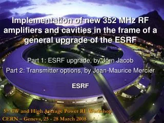
Introduction The development of the new 352 MHz cavity for the ESRF is based on the 500 MHz European HOM damped normal conducting cavity. Tuner Coupler Cavity body HOM damper Vacuum pump 2 Anna Triantafyllou-E.S.R.F. 13th ESLS RF Meeting, Desy, Hamburg, 30th September - 1st October 2009
Introduction • New ESRF cavities objectives : • 300 mA of beam current : - Design margin in terms of power per coupler window : 500 mA of stored beam. - Design margin in terms of HOM damping : 1A of bunch instability threshold to anticipate possible discrepancies between numerical and experimental data. • 9 MV of accelerating voltage : - Installation of 18 new single-cell cavities. - The system should be operational with 12 cavities. 3 Anna Triantafyllou-E.S.R.F. 13th ESLS RF Meeting, Desy, Hamburg, 30th September - 1st October 2009
Length before C48 ferrites = 840 mm 1 damper for the remaining HOMs : fc = 1.05 GHz d = 160 mm Dissipated power @ 352 MHz < 100 Watt 2 dampers not in the same plane : to avoid the high impedance 758 MHz mode measured on the previous prototype • 2 dampers • for the lowest • HOMs : fc = 452 MHz • d = 230 mm The vacuum pump port is not degrading the quality factor Aluminum prototype • Design optimization : 4 Anna Triantafyllou-E.S.R.F. 13th ESLS RF Meeting, Desy, Hamburg, 30th September - 1st October 2009
Aluminum prototype • Validation of the numerical model : Ridge width = 60 mm • Good correlation between measured and calculated data. • All the measured impedances of the HOMs are lower than the L.C.B.I. @ 352 MHz : Rs/Q =145 QCu : 30 k Rs=4.35 MΩ 5 Anna Triantafyllou-E.S.R.F. 13th ESLS RF Meeting, Desy, Hamburg, 30th September - 1st October 2009
In the ridge zones, the electrical continuity will be established by means of RF fingers. Coupling section e-beam welded to the cavity body. Coupling section Intermediate section Absorber Copper prototype • Design aspects • The gap problems between the ridges and the cavity body are eliminated by splitting the HOM dampers in three parts. 6 Anna Triantafyllou-E.S.R.F. 13th ESLS RF Meeting, Desy, Hamburg, 30th September - 1st October 2009
Cooling channels Copper prototype • Design aspects • In house design of the cooling system. Heat flux computed for the degraded operation 9MV with 12 cavities : Maximum temperature : 56°C *Thanks to Lin Zhang for his advice in thermal computations 7 Anna Triantafyllou-E.S.R.F. 13th ESLS RF Meeting, Desy, Hamburg, 30th September - 1st October 2009
e- 1. Machining of the pieces Coupling section e- Cavity body constant 15 mm thickness all around the e-beam welding Beam stop: will be removed after welding by turning 2.The gap is avoided by splitting the dampers in three parts. The first part is e- beam welded to the body. Copper prototype • Establishment of technological process (1/3) 8 Anna Triantafyllou-E.S.R.F. 13th ESLS RF Meeting, Desy, Hamburg, 30th September - 1st October 2009
Brazing of the S.S. and the Cu Turning this assembly TIG welding of the flanges 3.The vacuum flanges, outlets and pipes are brazed in a single step Copper plating the SS surface Copper prototype • Establishment of technological process (2/3) 9 Anna Triantafyllou-E.S.R.F. 13th ESLS RF Meeting, Desy, Hamburg, 30th September - 1st October 2009
Frequency tuning by machining the end disc Brazing of C48 ferrites on Copper Intermediate coupling sections Machining of the end discs Brazing step to attach the cooling system and the outlets. TIG welding of the Cover. Brazing on the ridges The end discs are added in a last brazing step. Brazing of the vacuum flanges and the cooling system. Copper prototype • Establishment of technological process (3/3) 10 Anna Triantafyllou-E.S.R.F. 13th ESLS RF Meeting, Desy, Hamburg, 30th September - 1st October 2009
Coupling sections and outlets are joined by e beam from the internal face. - e beam welding to join the angles. - e beam welding for the end discs after the frequency tuning steps. e- e beam welding to add the water box covers in each part. Machining of the cooling system in each part. Division of the cavity body in 3 parts e beam welding for the 3 shells assembly Outlets brazing before the cavity assembly Copper prototype • Alternative Fabrication process 11 Anna Triantafyllou-E.S.R.F. 13th ESLS RF Meeting, Desy, Hamburg, 30th September - 1st October 2009
40 MPa < Stress < 57 MPa Stress < 27 MPa The Maximum stress computed in the e beam weld area is reduced by increasing the e beam welding surface. Copper prototype • Stress calculation : - max water pressure = 15 Bars 12 Anna Triantafyllou-E.S.R.F. 13th ESLS RF Meeting, Desy, Hamburg, 30th September - 1st October 2009
Conclusions and Perspectives • Validation of the simulation model by an aluminum prototype. • Two different fabrication processes for the power prototype. • Ferrite infra red test bench under development. • Delivery of three prototypes expected by the end of 2010 followed by tests. 13 Anna Triantafyllou-E.S.R.F. 13th ESLS RF Meeting, Desy, Hamburg, 30th September - 1st October 2009