Download
1 / 48
480 likes | 560 Views
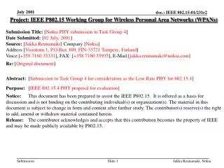
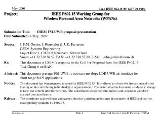
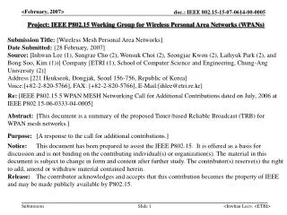
Project: IEEE P802.15 Working Group for Wireless Personal Area Networks (WPANs) Submission Title: [STMicroelectronics proposal for IEEE 802.15.3a Alt PHY ] Date Submitted: [03 March, 2003] Source: [ Philippe Rouzet (Primary) Didier Helal (Secondary) ] Company [ STMicroelectronics ]

E N D
Project: IEEE P802.15 Working Group for Wireless Personal Area Networks (WPANs) Submission Title: [STMicroelectronics proposal for IEEE 802.15.3a Alt PHY] Date Submitted: [03 March, 2003] Source: [Philippe Rouzet (Primary) Didier Helal (Secondary)] Company [STMicroelectronics] Address [STMicroelectronics, 39 Chemin du Champ des Filles 1228 Geneve Plan-les-Ouates, Switzerland] Voice [+41 22 929 58 72 or +41 22 929 58 66], Fax [+41 22 929 29 70], E-Mail:[didier.helal@st.com, philippe rouzet@st.com] Re: [This is a response to IEEE P802.15 Alternate PHY Call For Proposals dated 17 January 2003 under number IEEE P802.15-02/372r8 ] Abstract: [This document contents the proposal submitted by ST for an IEEE P802.15 Alternate PHY based on UWB technique.] Purpose: [Presentation to be made during March IEEE TG3a session in Dallas, Texas] Notice: This document has been prepared to assist the IEEE P802.15. It is offered as a basis for discussion and is not binding on the contributing individual(s) or organization(s). The material in this document is subject to change in form and content after further study. The contributor(s) reserve(s) the right to add, amend or withdraw material contained herein. Release: The contributor acknowledges and accepts that this contribution becomes the property of IEEE and may be made publicly available by P802.15. Didier Helal and Philippe Rouzet, STM
IEEE 802.15.3a Alternate PHY STMicroelectronics Proposal for March 2003, Dallas, Texas Didier Helal and Philippe Rouzet, STM
Contents • UWB PHY Proposal • Modulation and Principle • System Block Diagram • Assets • Performances at 110Mb/s • PHY protocol Criteria • MAC protocol Enhancement Criteria • General Solution Criteria Didier Helal and Philippe Rouzet, STM
Proposed Modulation Pulse Position + Polarity Modulation 1 to Np positions +1 / -1 Number of bits per pulse = 1+log2(Np) Positive Polarity Negative Polarity Position 1 Position 2 Position Np Didier Helal and Philippe Rouzet, STM
Flexible Modulation for data rate scalability Adaptive Pulse Repetition Period Didier Helal and Philippe Rouzet, STM
Training sequence Modulated user data Known Training Sequenceinserted into frame preamble Example of a simplified emitted pulse train Pulse shape not shown (use rectangle for clarity) PRP (Pulse Repetition Period) Time Hopping +Polarity 2-PPM +Polarity (Time Hopping optional) Didier Helal and Philippe Rouzet, STM
Demodulation is performed by Match-Filtering Demodulation Rx signal Match-filtering The match-filter is the estimate of the pulse signature through channel propagation No pulse shape is assumed by receiver ! Take advantage of multi-path (complete immunity) Tx signal Channel Estimation Average Compound Channel Response Channel+ Noise Didier Helal and Philippe Rouzet, STM
Proposed Alternate PHY enablesSingle Chip FULL CMOS solution Through DIRECT SAMPLING on 1 BIT DIGITAL MATCHED FILTERING Learn pulse signature after channel propagation Didier Helal and Philippe Rouzet, STM
Compliant with existing MAC IEEE 802.15.3 Introduction of minor adaptations to optimize receiver power consumption and complexity • MCTAs and Slotted Aloha used instead of CAP (CCA difficult with UWB-PHY) • Approximate frames Times Of Arrival (TOAs) • Announced by source DEV at the begining of CTA • Used for channel estimation & synchronization Didier Helal and Philippe Rouzet, STM
Optional Antenna Pulse Generator ABR BP Filter ABR TDD PTC Clock Synthesizer Switch 1-bit ADC LNA RF block UWB System-on-Chip Block Diagram TX Data Frag-mentation TX Preparation Channel Coding Modulation & coding TX Control PTC Channel estimation Synchronization RX Control Demodulation Channel Decoding Defrag- mentation RX Data MAC block (Bottom part) Baseband block PTC = Piconet Time Control ABR = Adaptive Band Rejection MAC+ BB+RF on same silicon except BP filter and Antenna Didier Helal and Philippe Rouzet, STM
Proposal forIEEE 802.15.3a Alternate PHY Performances at 110Mb/s Didier Helal and Philippe Rouzet, STM
Typical Pulse Shape BW-10dB = 7GHz Didier Helal and Philippe Rouzet, STM
ABR BP Filter ABR Link Budget at 110Mb/s at 10m Noise figure for all RX chain referred at the antenna output Optional Antenna Pulse Generator TDD Switch Clock Synthesizer 2dB loss 1dB loss G = 16dB 1-bit ADC LNA NF = 3.5dB 2dB NF = 9dB Implementation loss 5dB = 3dB due to jitter (<10ps rms) + 2dB margin Didier Helal and Philippe Rouzet, STM
System Performances 20Gsamples/s 1-bit ADC PER PER Eb/No Eb/No CM3 Channels, Turbo Code (2/3) PRP = 12ns, 2PPM + pol CM4 Channels, Turbo Code (1/3) PRP = 6ns, 2PPM + pol Didier Helal and Philippe Rouzet, STM
PHY-SAP Data Throughput close toPayload Bit Rate Optimized Packet Overhead Times PHY Header, MAC Header (802.15.3 format), HCS use 110Mb/s mode Didier Helal and Philippe Rouzet, STM
Signal Acquisition in superframeStep 1 : Coarse synchronization during Beacon Preamble. • Acquisition sequence : Quadratic-Congruence Hadamard Good cross-correlation and spectral properties Minimize ISI effect Max. length L = 2000 pulses; PRP = 10ns; Max. duration = 20 s • False Alarm Probability = 10-4 • Miss Detection Probability = 10 –4 Acquisition Didier Helal and Philippe Rouzet, STM
TOA 4 TOA 3 TOA 2 TOA 5 TOA 1 TOA 6 Step 2 : Fine synchronization only during Frame Preamble • Joint Channel Estimation and Fine Synchronization • Estimation valid during channel stationnarity (1ms) • Quadratic-Congruence Hadamard sequences : 3 s • Use of approximate frame TOAs to manage different lengths of frames MIFS MIFS MIFS MIFS MIFS Frame 4 Frame 5 3 6 MIFS MIFS Frame 1 Frame 2 CTA slot in superframe TOA 1 TOA 2 TOA 3 TOA 4 TOA 5 TOA 6 CTA Header announcing TOAs Didier Helal and Philippe Rouzet, STM
Simultaneously operating Piconets piconet 1 dmin TX DEV RX DEV piconet 2 multipath channel, 10m dmin dmin piconet 3 • Fine synchronization / Channel estimation /Demodulation • UWB interferers transmit continuously through multipath CM1 channel • RX Power = RX sensitivity + 6dB dmin = 1.7 m Coarse synchronization Didier Helal and Philippe Rouzet, STM
Adaptive channel coding • Turbo codes PCCC (Parallel Concatenation of Convolutionnal Codes) • Code rate 1/3. With puncturing:1/2, 2/3,7/8. • RSC (recursive systematic convolutional) 13,15(octal def.). • Block size: 512. • Low latency : 5 s • Optional Convolutional codes for lower complexity • Code rate 1/2. With puncturing:2/3,7/8 • Constraint length: 7 -> [133,171] Didier Helal and Philippe Rouzet, STM
Interference and Susceptibility System supports low Signal-to-Interferer-Ratios : SIR > -50dB for any in-band narrow-band Interferer • Adaptive Band Rejection 802.11a OFDM interferer : SIR>-30dB (at 5.3GHz or other) Generic in-band interferer : SIR>-30dB (at any frequency) • BaseBand Filtering rejection : SIR > -20dB All out-of-band interferers supported (according to IEEE 802.15-3a proposed criteria). Didier Helal and Philippe Rouzet, STM
Low Power Consumption • Baseband MODEM down to 220 kGates in 2PPM at 82.6MHz. • 60% gates in stand-by during 90% of time (channel est.) • Plus CODEC (60k to 500 kGates depending on architecture) • Power consumption of RF: RX< 70mW - TX < 40mW Full Scalability • Data throughput is adjustable (flexible modulation) • Compatibility between HDR and LDR devices • Multi-operating piconets supported • Complexity decreases along with data rate • Power consumption decreases with data rate Didier Helal and Philippe Rouzet, STM
Coexistence and regulatory impact • Coexistence with in-band systems ensured by TX pulse shaping or filtering • System is independent from pulse shape • Transmit power control reduces interferences • Helped by location awareness capability (distance can be estimated with 3cm resolution) • No impact on current regulation • FCC’s Part 15 rules followed • Additional spectrum protection can be supported • 802.15.3 Power Management modes are supported (DSPS, PSPS, APS) Didier Helal and Philippe Rouzet, STM
Easy Manufacturability and attractive form factor • Full system can be built in CMOS technology • single chip • Die size estimated at less than 5mm2 in 0.13m • Antenna size : expected 3cm x 3cm Time to Market can be less than 1.5 years ! System matches all criteria ! Didier Helal and Philippe Rouzet, STM
BACKUP SLIDES Didier Helal and Philippe Rouzet, STM
Channel Estimation Algorithm • The channel response is estimated with the training sequence • Coherent integrations (on the received pulses) reduces noise and ISI effects. • Most of channel energy is recovered by so. • SNR at RX is good enough to reduce PRP and to increase data rate. • System is independent from transmitted pulse shape • No need for Pulse Template Didier Helal and Philippe Rouzet, STM
channel decoding architecture Uncorrelates bit errors at the input of the decoder : C=code rate BTC=Turbo code block length. demapping and soft A priori per bit Probability calculations. Adds scalability Channel estimation depuncture channel decoder (Turbo decoder or Viterbi decoder) NPPM Correlations Deinterleaving BL=BTC/C descrambling APP calculations RF N-PPM (number of Pulse positions) soft values corresponding to each PPM position at Pulse Repetition Frequency. Didier Helal and Philippe Rouzet, STM
Turbo code • Latency is mainly due to the storage of one block into the channel de-interleaver. @110Mbps: 512/110e6~5us. @ 55Mbps: 512/55e6=10us. • Complexity: • RAM: 50 000 bits. • ~500 kGates (Current estimation). Didier Helal and Philippe Rouzet, STM
Outline • MAC Considerations • Sequence design • Coarse Synchronization • Fine Synchronization • Clock Synchronization • Timeline Didier Helal and Philippe Rouzet, STM
Coarse Synch • Detection • Alignement Fine Synch PNC tells DEV-A and DEV-B that DEV-B will send data to DEV-A in CTA x. Frame sent to DEV-A by DEV-B DEV-A and DEV-B are synchronized to PNC’s clock Preamble Body Header Frame Synch:Fine Synchonly (made jointly with ch.est.) Clock Synch DEV-A wakes up, and needs to synchronize to DEV-B’s clock. DEV-A’s clock is synchronized to DEV-B’s clock, and can start to demodulate the data contained in the frame sent by DEV-B. Cell Synch =Coarse+Fine+ Clock Scenario MAC considerations Cell synch Cell synch Frame synch Superframe N Superframe N+1 Contention Free Period Beacon Contention Access Period MCTA 1 preamble CTA m header body CTA 2 CTA x MCTA n CTA 1 preamble … … … … Didier Helal and Philippe Rouzet, STM
Preamble Training Sequence Design • Quadratic-Congruence Hadamard sequences • TH positions: • Polarity: derived from row of a Hadamard matrix of size (L ± 1) x (L ± 1) • Used both for beacon training sequences and for frame training sequences • L: length of sequence • i = 1,2,…,L-1: sequence number • n = 0,1,…,L-1: TH offset index Good spectral properties e.g. 11 dB smoother spectrum Compared to any TH code with L =79 Good peak to side-lobe ratio: L/2e.g. 16 dB with L = 79 80 70 0 60 -5 -10 50 -15 40 -20 dB 30 -25 -30 20 -35 10 -40 0 -45 -50 -10 -0.5 0 0.5 0 1000 2000 3000 4000 5000 6000 7000 f*T p Autocorrelation function for L=79 Spectrum with TH + polarity, L=79 Didier Helal and Philippe Rouzet, STM
Coarse synchronization • Hypotheses • No clock jitter present • No clock drift present • Send at max power allowed by FCC • Maximum beacon training sequence length: 20 s • Superframe ~= 10 ms • 4 scenari studied • CM3 channels utilised • Performance Indicators • False Alarm probability (PFA): a preamble is detected where there is none • A target PFA ~ 10-4 is assumed • Missed Detection probability (PMD): the preamble is not detected • A target PMD ~ 10-4 is assumed • Beacon training sequence length • ~ overhead percentage • ~ synchronization time Didier Helal and Philippe Rouzet, STM
L=50 L=100 L=200 L=400 L=800 L=1600 L=3200 PMD vs. SNR, for different beacon training sequence lengths, no jitter, CM3; PFA = 10-4 (constant); PRP = 10 ns 0 10 -1 10 -2 10 Max expected loss due to jitter: 1-2dB D M P -3 10 -23.3 -10.9 -17.2 -3.1 -4 10 -13.9 -7.2 -20.3 -5 10 -25 -20 -15 -10 -5 0 SNR [dB] Didier Helal and Philippe Rouzet, STM
PNC DEV Free space AWGN channel,10 m Coarse synch: Scenario 1 Detectability D1 = Ps -Pn –NF –Gjitter +Gduty-cycle = -73 +75 –7-2 + 20 = 13 dB • For meeting target performances: • sequence length needed L = 48 • PRP = 10 ns => sequence duration = 48*10ns = 480 ns • Pulse width = 100ps Didier Helal and Philippe Rouzet, STM
piconet 1 d PNC DEV piconet 2 Free space AWGN channel,10 m d d piconet 3 Coarse synch: Scenario 2 Detectability D2 = -10log10(3) - 20log10(10/d) –NF –Gjitter + Gduty-cycle = = -13.77 dB + 20log10(d) • Use largest beacon training sequence allowed: 20 s • PRP = 10 ns => L = 2000 • Dtarget = -10.3 dB dmin = 1.50 m Didier Helal and Philippe Rouzet, STM
PNC DEV multipath channel,10 m Coarse synch: Scenario 3 Detectability D3 = D1 +Gchannel +Gmultipath = 13 +8.5 = 4.5 dB • For meeting target performances: beacon training sequence length needed L = 90 • PRP = 10 ns => sequence duration = 90*10ns = 900 ns Didier Helal and Philippe Rouzet, STM
piconet 1 d PNC DEV multipath channel,10 m d d piconet 3 Coarse synch: Scenario 4 piconet 2 Detectability D4 = D2 + Gmultipath = -22.27 dB + 20log10(d) • Use largest beacon training sequence allowed: 20 s • PRP = 10 ns => L = 2000 • Dtarget = -10.3 dB dmin = 4 m Didier Helal and Philippe Rouzet, STM
Channel estimation Simulation Results • Loss due to reduction of training sequence length from 6s to 3s equal to 1dB Didier Helal and Philippe Rouzet, STM
Clock synchronization • Goal: align DEV’s clock frequency to PNC’s (drift correction) • Continuously performed over subsequent superframe beacon preambles • Filter correction feedback 1 0.8 0.6 0.4 0.2 Normalized Amplitude 0 76 [ps] -0.2 -0.4 -0.6 -0.8 -0.25 -0.2 -0.15 -0.1 -0.05 0 0.05 0.1 0.15 0.2 0.25 Time [ns] Pulse autocorrelation function Didier Helal and Philippe Rouzet, STM
Timeline • Coarse synchronization: • Assumed number of different beacon training sequences for PNCs: 8 • DEVs search in a serial manner one among the 8 sequences • At each superframe, one new sequence is searched for • Superframe length ~= 10 ms worst search time = 80 ms • Clock synchronization: • Is performed continuously, based on beacon training sequences • Frame synchronization: • Performed on frame training sequence • If failed, frame is lost Didier Helal and Philippe Rouzet, STM
Pulse Repetition Period at 110Mb/s CR = Code Rate All PRP values in nanosecond Low order modulation preferred to minimize gate count/cost for low data-rate devices Didier Helal and Philippe Rouzet, STM
Pulse Repetition Period at 200Mb/s CR = Code Rate All PRP values in nanosecond Low order modulation preferred to enable intermediate data-rate devices Didier Helal and Philippe Rouzet, STM
Pulse Repetition Period at 480Mb/s CR = Code Rate All PRP values in nanosecond Larger PRP preferred to avoid too small inter-position delay ! Didier Helal and Philippe Rouzet, STM
Manufacturability • Architecture matches full CMOS implementation • Low cost, single chip product • Using today’s silicon technology • Simulation proven hardware architecture • SystemC model used • Performance and gate complexity estimated • Demonstrator in development • 0.13 m CMOS technology • Size and form factor • Single chip silicon allows small size like PC card, memory stick, …, and would be usable in portable devices Didier Helal and Philippe Rouzet, STM
Estimated Gate Count (DEMOD) Didier Helal and Philippe Rouzet, STM
Power consumption • Low power Architecture • Minimum RF front end (low power with respect to alternative architecture) • Demodulation processed in digital • Channel estimation gates (~2/3 of demodulation count) used only during frame preamble (<10% of time) • Typical clock frequency is PRP (only RF front end is high speed) • Digital power consumption will scale as Moore’s law in future technology Didier Helal and Philippe Rouzet, STM
Scalability • Low data rate (LDR) permits lower power, lower complexity • Channel estimation power cost can be reduced for low data rate (need less path, and shorter sequence) • Simple modulation (polarity) compatible with HDR devices • High data rate scalable easily • ST expect data rate of up to 750 Mbps shortly • 1 Gbps theoretically possible Didier Helal and Philippe Rouzet, STM
Location awareness • Relative location (distance between stations) available at almost no cost • Thanks to channel estimation principle • 2 performance levels possible (implementor choice) • A few decimeters accuracy (simple processing) • A few centimeters accuracy (signal processing of estimated channel) • Minimal additional hooks in 802.15.3 MAC Didier Helal and Philippe Rouzet, STM
Multipath immunity • Channel estimation principle allows capture of most received energy • Equivalent to infinite rake architecture • Excellent performance in worst multipath environment • Pulse shape/spectrum independent • The receiver architecture don’t need a-priori knowledge on pulse shape (this is why it is so easy to match specific regulation) • Dense multipath channel with overlapping pulses don’t degrade performance Didier Helal and Philippe Rouzet, STM