Download
1 / 39
390 likes | 485 Views
G 0 Forward Angle Measurement and the Strange Sea of the Proton. Kazutaka Nakahara. Strangeness (briefly) Parity violation G0 Experiment Physics results. SLAC Seminar 1/19/06. Proton Structure. 3 valence quarks not a bad approx. at high energies

E N D
G0 Forward Angle Measurement and the Strange Sea of the Proton Kazutaka Nakahara Strangeness (briefly) Parity violation G0 Experiment Physics results SLAC Seminar 1/19/06
Proton Structure 3 valence quarks not a bad approx. at high energies At low energy, things get messy. Sea includes gluons and “sea quarks”, and can contribute to proton structure Strange quarks give exclusive insight into the sea and come in pairs no net strangeness
Hadronic Current EM coupling to pointlike fermion Represents internal structure of the proton Sach’s FF ~ p, rp at q2=0 ~ Fourier transform of the charge and magnetization distribution of the proton.
charge symmetry 2. = Neutron EM form factor 3. Measure the neutral weak proton form factor Access the neutral weak sector of elastic e-p scattering Want to know and Nucleon Form Factors 1. = Proton EM form factor
Parity Violation can be determined through parity-violating elastic e-p scattering. Parity Conserving Parity Violating Measure asymmetry in elastic e-p cross section for + and – helicity incident electrons. -3 to -40 ppm measurement!!
Measure at forward angles (elastic e-p) Measure at backward angles (elastic e-p and quasi-elastic e-d) Parity Violation Proton Form Factors Can QCD tell us these things? In principle, yes. But hard to calculate.
Most calculations attempt to calculate s. Theoretical Predictions Loops Poles Lattice Other Maybe negative, but not much consensus...try measuring.
Previous PV Experiments • Mostly low Q2 to probe the proton’s static (Q2 = 0) properties.
Jefferson Laboratory linacs Injector/Source A C B
G0 Experiment Overview Ebeam = 3.03 GeV, 0.33 - 0.93 GeV Ibeam = 40 mA, 80 mA Pbeam = 75%, 80% q = 52 – 760, 104 - 1160 DW = 0.9 sr, 0.5 sr ltarget = 20 cm L = 2.1, 4.2 x 1038 cm-2 s-1 A ~ -1 to -50 ppm, -12 to -70 ppm • Measure and at different Q2. - Gives different linear combination of u, d, and s contributions. • Measure asymmetries at forward and backward angles. - Forward angles recoil protons - Backward angles elastic and quasi-elastic electrons Separates electric and magnetic contributions. • Forward angle measurement complete (101 Coulombs)
elastic protons detectors lead collimators beam target G0 Spectrometer (forward mode) • 40 A polarized electron beam at 3 GeV • High power LH2 target • Toroidal superconducting magnet (5000A, 1.6 T-m) • High rate counting electronis~ 1 MHz / detector deadtime well understood • 0.12 < Q2 < 1.0 (GeV/c)2
superconducting magnet (SMS) G0 in Hall C (JLab) cryogenic supply beam monitoring girder scintillation detectors cryogenic target ‘service module’ electron beamline
JLab Accelerator 3 endstations. One laser for each hall shining a common GaAs cathode 1497 MHz SRF cavities Each hall receives beam at 499 MHz simultaneous 3 hall delivery possible. ~ 600 MeV / linac, 2 linacs per “pass” with up to 5 passes possible. RF separator + Lambertson kicks beam into the correct hall.
40 A at 3 GeV • Usual beam pulse at Jlab is 2 ns (499 MHz). G0 beam pulse = 32 ns (31 MHz) high bunch charge • Helicity-flip every 1/30 sec (macropulse). • Macropulse arrange in quartet pattern asymmetry from each quartet • Must control helicity-correlation in beam properties (I,X,Y,x,y,E) Beam Structure
Helicity-Correlated Beam Feedback shows convergence of HC beam properties
G0 Data Overview Final Data: 701 h at 40 A (101C) 19 x 106 quartets 76 x 106 MPS Integrate yield over elastic region for + and – helicities ...done? Not so fast Various systematic effects must be corrected.
Raw Asymmetries, Ameas Aphys GE GM + h s s Analysis Overview Blinding Factor “Beam” corrections: Leakage beam asymmetry Helicity-correlated beam properties Deadtime Beam polarization Background correction Q2 EM form factors
Helicity-Correlated Beam Parameters • Sensitivity of detector to beam fluctuations, , well understood. • Run-averaged HC beam parameters are small. • False asymmetry ~ 0.02 ppm. - 100x to 1000x smaller than the smallest physics asymmetry measured in G0 - Significantly smaller than the 5-10% total uncertainty expected for G0.
499 MHz beam leaks into G0 beam. (~40-50 nA). Comes from “inperfect” diode (poor) and Ti-Sapphire (better) lasers not shutting off fast enough. 2ns “background” spectra under the G0 spectra. • Large charge asymmetry associated with leakage current. (A ~ 600ppm) • BCMs integrate charge insensitive to micro-structure, Beam Leakage Current 32 ns G0 beamOnly 1 out of 16 buckets should be filled!! 2ns ~ 1.6 pC G0 beam pulse 32ns Use cut0 region to determine the leakage asymmetry. Agrees with leakage-only runs. Aleak = -0.71 0.14 ppm (global uncertainty)
Background Subtraction 2 step fitting procedure: • Fit the yield spectra, and determine the background fraction, f(t), (e.g. background rate / total rate) bin by bin • Fit asymmetry with, Background asymmetry Elastic Asymmetry Model: Gaussian Yel, constant Ael Pol’4 Ybkg, Pol’2 Abkg
G0 Physics Asymmetries No “vector strange” asymmetry, ANVS, is A(GEs,GMs=0) Inner error band is stat., outer band is stat. + pt-pt. Global error band dominated by leakage and background corrections. Forward angle results: http://www.npl.uiuc.edu/exp/G0/Forward
Strange Quark Contribution “Kelly form factors”: Kelly PRC 70 (2004) 068202
G0 Forward Angle Results Forward angle results over 0.12 < Q2 < 1.0 GeV2. Model uncertainty from EW radiative corrections. 3 types of nucleon form factors shift in baseline No-vector-strange hypothesis disfavored at 89%.
= -0.013 0.028 = +0.62 0.31 Q2 = 0.1 GeV2 World data at Q2 = 0.1 including G0. GEs and GMs:
Q2 = 0.23 GeV2 • Negative ? Need more data • Backward angle measurement scheduled (G0 and PVA4)
Summary • Forward angle measurement shows consistency with previous experiments • Strange quarks do appear to contribute to the static properties of the proton. • Interesting Q2 dependence • Backward angle measurements scheduled for 2006/2007.
Things to add Results: • evolution of eta across Q2 • Explanation of the “dip” • Higher Q2 point band plots • Add plot of “where we were”...consider moving the band plot with no G0 to somewhere near here. Apparatus: • Explain “quartet”, pulse length (tof?), etc, somewhere...before beam stuff or after? Analysis 1. Show chi2 of background fits. Intro: • Explain where form factors come from? p6. Too cluttered. Try creating animation.
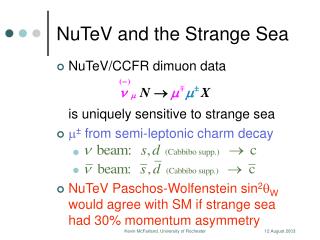
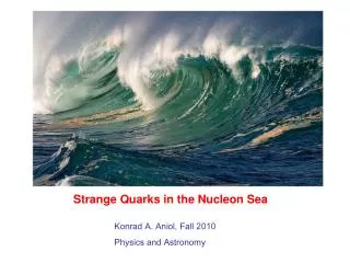
Strange Quarks in the Proton? Proton is the only known stable hadron. Extensively studied, but the details of its composition is not well known. • Spin contributions • Mass contributions N- term • Momentum Distribution NuTeV • Charge and magnetization distribution. Measure through Parity-Violation EMC
Previous Experiments at Q2=0.1 World Data: Each was at different angular kinematics. GMs=0.550.28 GEs =-0.010.03 1 contour 95.5% CI
Polarized Electron Beam • 40 A of polarized electron beam • Helicity-correlated beam properties (I,X,Y,x,y,E) must be minimized!! Minimize through active IA (charge) and PZT (position) feedback.
Target • 20 cm LH2, aluminum target cell • longitudinal flow, v ~ 8 m/s, P > 1000 W! • negligible density change < 1.5% • measured small boiling contribution • 260 ppm/1200 ppm statistical width
Magnet • 8 coil superconducting torus • single cryostat • 5000 A, 144 turns/coil; 5.8 MA-turns, total • stored energy ~ 5.5 MJ • field integral ~ 1.5 T·m • bend angle 35 – 87o • lead collimators for , acceptances • acceptance 44% of 2 • line-of-sight shielding for neutrons
PMT Left Mean Timer Front PMT Right TDC / LTD Scalers: Histogramming Coinc PMT Left Mean Timer Back PMT Right Particle identification through TOF separation. Detect four-fold coincidence hits. Fast counting electronics (~1MHz per detector). G0 Electronics
Electronics Deadtime Measurements • Deadtime at three stages • CFD, mean-timer, coincidence • scale CFD, mean-timer rates • measure coincidence deadtime directly with “buddy” system • e.g. oct. 5. det. 4 with oct. 1, det. 4 • careful treatment of combined effects • Comparison • from measured components above • from slope of yield asymmetry vs. charge asymmetry • from large induced charge asymmetry runs (~1000 ppm) • consistent with measurements of yield as function of beam current
Background Subtraction (Det15) Interpolate asymetries and yields over detectors 12 through 16 (for each timebin). Yields: Linear interpolation, ±0.5 “detector” as uncertainty. Asymmetries: Smooth interpolation from lower detectors, ±1 “detector” and ± 0.5 ns time shift as uncertainty Result shows good agreement with sideband asymmetries.
Fit suggests a positive and a negative bump in . Is this model realistic or too simplistic? There are some preliminary results that may support this claim. Otherwise, stay tuned for more results! Fit of G0Data • : parametrized in a fasion similar to “Kelly” form factors. • : dipole form used