Download
1 / 17
170 likes | 309 Views
Jitter and Phasenoise Devices simulation. Jitter is a measurement of the variations in the time domain, and essentially describes how far the signal period has wandered from its ideal value. Typically, deviations below 10 MHz are not classified as jitter, but as wander or drift.

E N D
Jitter and Phasenoise • Devices • simulation
Jitter is a measurement of the variations in the time domain, and essentially describes how far the signal period has wandered from its ideal value. Typically, deviations below 10 MHz are not classified as jitter, but as wander or drift. Phase noise is a frequency-domain view of the noise spectrum around the oscillator signal, while jitter is a timedomain measure of the timing accuracy of the oscillator period Problem: There exist many similar definitions – same word describes different things!
Absolute jitter: It is given by the sum of each periods variation from the average Period jitter:simply measures the period of each clock cycle in the waveform Cycle-to-cycle jitter: This is the jitter definition that most people mean when they talk about jitter as a single number. It measures the variance of each period to the average period:
Phasenoise: Measuring phasenoise
Translating between phasenoise and jitter The total noise power of the sidebands can be determined by integrating the L(f) function over the band of interest - in this case, 12 KHz to 10 MHz. This might be for example be the case if low frequency noise = ”‘slow”’drifts are not of importance.
What are our frequency - boundaries? • TTC (Timing, Trigger and Control) is only the delivery system: Info about timing to beam?
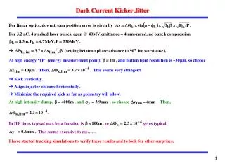
Pulsed BBLR: Load: L = Zin/2f of 840nH. Design strategy
Remo Maccaferri • – has specs, thinking of avalache devices (as far as I know) advantage: high current, fast switching, disadvantage: lifetime, fuzzy status, problematic to turn off • 2) M. Paoluzzi • - no avalanche devices (fuzzy state, but knows he is no expert on them) • - he thinks its possible to meet the specs with: • Transitor:polyfet rf devices - F1401 • Gatedriver: IXYS- IXDD415SI • -spice models avaiable, to be tested.
Simulations: SPS – DA as function of beam-wire distance - which law? The simulated dependance on the beam-wire distance is fitted by y = a*x^b + c, where a = 0.188, b = 1.836, c = 0.06768 -> The dependance always follows a power law.
- > Can we make test the power law in the SPS at different tunes?
Blue beam - L45, LR(s=0), t-comp, Qx=28.733, Qy=29.722 No sextupoles including sextupoles
Tune from one turn map ( included in BBTrack 5.3.0.3) Example: an instable particle
Is the tune difference a valid Lyaponov-function? • -> seams easier to detect. • What are the frequencies? Chromaticity=0, no sextupoles, offmomentum
Next steps • Chromaticity tuneshift? • Tune variation fue to coupling • ….