Download
1 / 35
350 likes | 611 Views
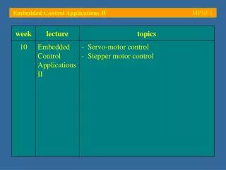
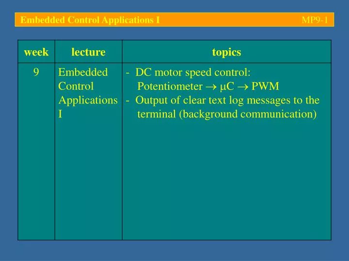
Embedded Control Applications I MP9- 1. Embedded Control Applications I MP9- 2. PWM control of a DC motor. - The control of a DC motor is very common task in robotics / mechatronics; the velocity of a DC motor is proportional to the applied DC voltage.

E N D
Embedded Control Applications I MP9-2 PWM control of a DC motor - The control of a DC motor is very common task in robotics / mechatronics; the velocity of a DC motor is proportional to the applied DC voltage - Microcontrollers usually do not come with on-chip D/A converters; therefore, a way has to be found to interface the microcontroller to the amplifier which drives the motor (H-bridge amplifier, transistor, etc.) - The most widely used approach is to produce a Pulse Width Modulated (PWM) signal and turn it into a DC-voltage by filtering out the DC component
Embedded Control Applications I MP9-3 PWM control of a DC motor - A PWM signal is a pulse sequence and, as such, it has an amplitude spectrum which can be described by the well-known sinc function(sin(x)/x) DC component 2.5f0 1.5f0 f0 2f0 3f0
Embedded Control Applications I MP9-4 PWM control of a DC motor - The amount of power concentrated at DC depends on the duty cycle (relative pulse width) 10% duty cycle 90% duty cycle average average
Embedded Control Applications I MP9-5 PWM control of a DC motor - Filtering PWM signal with a low-pass filter reduces it to its DC component – the amplitude of this DC signal is proportional to the duty cycle - The cut-off frequency of the filter has to be chosen with respect to the frequency of the PWM signal; a compromise between signal strength and residual ripple has to be found 50% duty cycle
Embedded Control Applications I MP9-6 PWM control of a DC motor - The inertia of the rotor of a DC motor presents a (mechanical) low-pass filter; many robotics application therefore pass the PWM signal straight to the motor – this works fine, provided the frequency of the PWM signal is sufficiently above the cut-off frequency of the low-pass characteristic of the motor - DC motor speed control using microcontrollers is therefore a straight-forward task - This lecture will outline how a simple speed control of a DC motor can be implemented on a C167
M Embedded Control Applications I MP9-7 PWM control of a DC motor A small DC-motor is to be driven using an edge aligned PWM signal on P7.3 (period: 100 ms). The duty cycle is to be controlled by the analogue voltage applied to ADC channel 4. This voltage should also be logged on a terminal connected to ASC port S0 (57600 bps) P5.4 5V PORT 5 PORT 7 PORT 3 0V RxD P7.3 TxD 0V
Embedded Control Applications I MP9-8 PWM control of a DC motor - All required software components have already been developed (PWM, ADC, serial communication routines); it is therefore just a matter of “putting the bits together” - Keeping functionally distinct parts of the program in separate modules (i. e. separate source code files) will greatly improve its readability and maintainability - The functions defined in one module are then made available to other modules via a header file which declares all public symbols (functions, globals, etc.)
Embedded Control Applications I MP9-9 Modular programming: Exporting shared symbols File: adc.c /* read ADC channel ‘chan’ */ unsigned int ADC_Read(unsigned int chan) { (…) } /* initialize ADC */ void ADC_Init(void) { (…) } File: main.c /* externally defined functions */ #include “adc.h” /* main */ void main(void) { (…) } File: adc.h /* declare ADC_Read */ extern unsigned int ADC_Read(unsigned int chan); /* declare ADC_Init */ extern void ADC_Init(void);
Embedded Control Applications I MP9-10 PWM control of a DC motor 4 source code files (modules) need to be defined: serial.c, pwm.c, adc.cand DCMot.c (the main program)
Embedded Control Applications I MP9-11 PWM control of a DC motor - Module serial.c takes care of the (background) communication with the host; all public functions defined in serial.c are declared to the calling modules in header file serial.h /* header file for serial.c, fw-01-02 */ #ifndef _SERIAL_H_ #define _SERIAL_H_ /* I/O interface */ void serInit(void); int serOutchar(char); char serInchar(void); int serOutstring(char *); void myPrintf(char *fmt, ...); #endif /* _SERIAL_H_ */ It is good programming style to avoid recursive inclusions; these three lines do just that The declaration of all public functions of serial.c…
Embedded Control Applications I MP9-12 PWM control of a DC motor - Module pwm.c takes care of the (background) generation of the PWM signal on port P7.3; all public functions defined in pwm.c are declared to the calling modules in header file pwm.h /* header file for pwm.c, fw-01-05 */ #ifndef _PWM_H_ #define _PWM_H_ #define PWMPERIOD (20e6/64)*100e-3 /* 100 ms */ void pwm_init(void); void pwm_set(unsigned int off_phase); #endif /* _PWM_H_ */ Macro PWMPERIOD has been moved into the header file to make it available to the calling modules
Embedded Control Applications I MP9-13 PWM control of a DC motor - Initialization and the setting of the duty cycle have been implemented in two separate functions: #include <reg167.h> #include "pwm.h" /* macro PWMPERIOD */ void pwm_init(void) { DP7 |= 0x08; /* P7.3 : output associated with CC7 (CC7IO) */ P7 &= ~0x08; /* set P7.3 low -> motor off */ PP3 = PWMPERIOD; /* initialize channel 3 period register */ PW3 = PWMPERIOD/2; /* initialize channel 3 pulse width register */ PWMCON1 = 0x0008; /* channel 3: edge aligned PWM, o/p enabled */ PWMCON0 = 0x0088; /* channel 3 operates of fCPU/64, timer is running */ }/* pwm_init */ void pwm_set(unsigned int off_phase) { PW3 = off_phase; /* initialize channel 3 pulse width register */ }/* pwm_set */
Embedded Control Applications I MP9-14 PWM control of a DC motor - Module adc.c takes care of the reading of ADC channel 4 (P5.4); all public functions defined in adc.c are declared to the calling modules in header file adc.h /* header file for adc.c, fw-02-05 */ #ifndef _ADC_H_ #define _ADC_H_ void adc_init(unsigned int channel); void adc_read(float *result); #endif /* _ADC_H_ */ - Module DCMotorController.c includes the header files of all of the above modules
Embedded Control Applications I MP9-15 PWM control of a DC motor - Initialization and the reading of the ADC result have been implemented in two separate functions: #include <reg167.h> /* reg167.h doesn't seem to define P5DIDIS... */ #define P5DIDIS (*((unsigned int volatile sdata *) 0xFFA4)) void adc_init(unsigned int channel) { P5DIDIS |= channel; /* disable input buffer in parallel w/h channel */ ADCON = channel; /* select channel for single conversion */ }/* adc_init */ void adc_read(float *result) { ADCON |= 0x0080; /* start ADC */ while(ADCON & 0x0100); /* loop in this line until ADBSY is clear */ /* retrieve result, eliminate channel number and rescale to 0 ... 5 */ *result = ((float)(ADDAT & 0x03FF))/1023*5; }/* adc_read */
Embedded Control Applications I MP9-16 PWM control of a DC motor - With these modules in place, the main program becomes very simple: #include <reg167.h> #include <math.h> /* fabs */ #include "serial.h" /* S0 communication routines */ #include "adc.h" /* adc_init, adc_read */ #include "pwm.h" /* pwm_init, pwm_set */ /* control of the on-board LED */ void blinky(long duration) { long i; DP2 |= 0x0001; /* make sure P2.0 is an output */ P2 &= ~0x0001; /* LED on (active low) */ for(i=0; i<duration; i++); /* wait (on phase) */ P2 |= 0x0001; /* LED off */ for(i=0; i<duration; i++); /* wait (off phase) */ } (…) Function blinky has been defined to flash the on-board LED (connected to port P2.0); it is used during the debugging stage of this project
Embedded Control Applications I MP9-17 PWM control of a DC motor (…) void main(void) { float myVoltage, myVoltage_old = 2.5; /* say hello... */ blinky(10000); serInit(); /* initialize S0, 1-N-57600 */ adc_init(4); /* initialize ADC channel 4 */ pwm_init(); /* initialize PWM unit */ IEN = 1; /* allow interrupts to happen */ /* display message */ myPrintf("\r\nDC Motor controller \n\r"); (…) - The call to function blinky reveals whether the target is running or not; this is particularly important when working on a new microcontroller and/or when modifying the settings of the startup module - The program initializes the serial interface ASC0, the ADC and the PWM unit; it then sends a welcome message to a terminal on ASC0
Embedded Control Applications I MP9-18 PWM control of a DC motor (…) while(1) { /* read ADC (channel 4) */ adc_read(&myVoltage); /* adjust duration of off_phase */ if(fabs(myVoltage_old-myVoltage) > 0.02) { /* flash LED to give some feedback */ blinky(1000); myPrintf("Voltage on channel 4: %1.2f volts\r\n", myVoltage); pwm_set((unsigned int)(myVoltage/5*PWMPERIOD)); myVoltage_old = myVoltage; } /* if */ } /* while */ } /* main */ ADC channel 4 is read and the result compared to the previously read value; if there is a difference of more than 0.02 V, the duty cycle of the PWM is changed and a log message is sent to the terminal
Embedded Control Applications I MP9-19 PWM control of a DC motor Simulation allows the program structure to be checked; however, its timing can only be checked on the real hardware
Embedded Control Applications I MP9-20 PWM control of a DC motor - A downloadable output file needs to be generated; the KEIL tools make use of the Intel HEX format
Embedded Control Applications I MP9-21 PWM control of a DC motor - The correct memory map has to be specified – this information is found in the manual of the dev. board
Embedded Control Applications I MP9-22 PWM control of a DC motor - Once generated, the HEX output file has to be burnt into the Flash EEPROM of the controller/board
Embedded Control Applications I MP9-23 PWM control of a DC motor - Finally, the program can be run out of Flash ROM – a hardware resetshould initialize the controller and divert execution to the destination address of the RESET vector; if everything has worked, this should be the startup routine which, in turn, calls main - This is where the on-board LED becomes an invaluable debugging tool – if it stays dark, then there is a problem with the initialization of the chip; the latter could be due to incorrectly set flags ( see startup file) or because of a problem with the memory map ( see linker map file)
Embedded Control Applications I MP9-24 PWM control of a DC motor - Assuming everything has worked properly, the terminal (57600 bps, 8/N, 1 stop bit, no protocol) should show the welcome message and possibly a few lines with voltage values - More values are printed when P5.3 is interfaced to an external voltage source (e.g. a potentiometer, between 0 and 5 V)
Embedded Control Applications I MP9-25 PWM control of a DC motor - The timing of the PWM signal can only be verified using an oscilloscope; on the phyCORE-167 all processor pins have been broken out to an expansion board – this is very useful to avoid short circuits… Verifying the timing of a PWM signal requires an oscilloscope; note that the requested period of 100 ms has been achieved; the picture shows a duty cycle of approximately 1/3 of the period (33 ms)
Embedded Control Applications I MP9-26 PWM control of a DC motor - Module adc.c could have used an Interrupt Service Routine (ISR)to read out the conversion result: (…) unsigned int ADC_result; /* global result register */ /* ADC interrupt service routine (ISR) */ void ADC_ISR(void) interrupt 0x28 { ADC_result = ADDAT & 0x03FF; /* fetch result and store in global */ } void adc_init(unsigned int channel) { P5DIDIS |= channel; /* disable input buffer in parallel w/h channel */ ADCON = channel|0x0090; /* select channel for continuous conversion */ ADCIC = 0x0044; /* enable ADC interrupt, ILVL = 1, GLVL = 0 */ } /* adc_init */ Note that the ADC has been set up for continuous conversion, i. e. the ADC is immediately restarted following the completion of a conversion
Embedded Control Applications I MP9-27 PWM control of a DC motor - The main program now simply processes the continuously updated global variable ADC_result (…) while(1) { /* read ADC (channel 4) */ myVoltage = (float)(ADC_result)/1023*5; /* adjust duration of off_phase */ if(fabs(myVoltage_old-myVoltage) > 0.02) { /* flash LED to give some feedback */ blinky(1000); myPrintf("Voltage on channel 4: %1.2f volts\r\n", myVoltage); pwm_set((unsigned int)(myVoltage/5*PWMPERIOD)); myVoltage_old = myVoltage; } /* if */ } /* while */ } /* main */
Embedded Control Applications I MP9-28 PWM control of a DC motor - Even better performance can be achieved using the so-called Peripheral Event Controller (PEC) - PECs implement a very fast Direct Memory Access (DMA) scheme; PEC transfers can transport one or more data bytes or words from a source area to a destination area - This transfer is extremely fast (a single CPU cycle!) and can simply be set up by specifying source and destination pointers and choosing the interrupt level (ILVL) which corresponds to PEC transfers
Embedded Control Applications I MP9-29 PWM control of a DC motor - Saving the ADC conversion result via PEC transfer on PEC channel 0 (ILVL: 14, GLVL: 0) (…) #include <reg167.h> #include <intrins.h> /* _sof_ : segment offset (-> segment 0) */ unsigned int ADC_result; /* global result variable */ void adc_init(unsigned int channel) { ADCON = channel|0x0090; /* select channel for continuous conversion */ SRCP0 = (unsigned int)&ADDAT; /* PEC0 transfer from ADDAT... */ DSTP0 = _sof_(&ADC_result); /* to ADC_result, 16-bit address, segment 0 */ PECC0 = 0x00FF; /* PEC0 Word transfer, continuous operation */ ADCIC = 0x0078; /* enable ADC -> PEC0 : .0011.1000 = 0x78 */ } /* adc_init */ The ADC Interrupt Service Routine is no longer required; PEC transfers only work with source/destination pointers in segment 0; operator _sof_ extracts the segment offset of a variable – this is what is required here
Embedded Control Applications I MP9-30 PWM control of a DC motor Simulation shows how the PEC operates; notice the almost permanent availability of ADC conversion data
Embedded Control Applications I MP9-31 PWM control of a DC motor - Upon downloading the modified code to the target the PWM appears to be stuck, i. e. it does no longer change with the voltage of the potentiometer - Considering that the program was working before, it must be suspected that the PEC transfer does not function as expected - A logical conclusion would be to look for the fault in the way memory is accessed; PEC transfers require linear 16-bit addresses in segment 0 – it is conceivable that variable ADC_result has not been placed there
Embedded Control Applications I MP9-32 PWM control of a DC motor - The linker map file confirms this suspicion: START STOP LENGTH TYPE RTYP ALIGN TGR GRP COMB CLASS SECTION NAME ===================================================================================== 000000H 000003H 000004H --- --- --- --- --- --- * INTVECTOR TABLE * 000004H 000013H 000010H XDATA REL WORD --- --- GLOB --- ?C_INITSEC 000014H 000023H 000010H CONST ABS WORD --- --- PRIV --- ?C_CLRMEMSEC 000024H 00007DH 00005AH DATA REL WORD --- --- PUBL FCONST ?FC??PRNFMT 00007EH 000099H 00001CH DATA REL BYTE --- --- PUBL FCONST ?FC?SERIAL 0000A8H 0000AFH 000008H --- --- --- --- --- --- * INTVECTOR TABLE * 0000B0H 0000ECH 00003DH DATA REL BYTE --- --- PUBL FCONST ?FC?DCMOTORCONTROLLER 0000EEH 00011DH 000030H DATA REL WORD --- 3 PUBL NCONST ?C_LIB_NCONST 00011EH 000243H 000126H CODE REL WORD --- --- PRIV ICODE ?C_STARTUP_CODE 000244H 000C39H 0009F6H CODE REL WORD --- 1 PUBL NCODE ?C_LIB_CODE 000C3AH 000F99H 000360H CODE REL WORD --- 1 PUBL NCODE ?PR?SERIAL 000F9AH 00107FH 0000E6H CODE REL WORD --- 1 PUBL NCODE ?PR?DCMOTORCONTROLLER 001080H 0010ADH 00002EH CODE REL WORD --- 1 PUBL NCODE ?PR?ADC 0010AEH 0010D3H 000026H CODE REL WORD --- 1 PUBL NCODE ?PR?FABS 0010D4H 0010F5H 000022H CODE REL WORD --- 1 PUBL NCODE ?PR?PWM 0010F6H 001105H 000010H CODE REL WORD --- 1 PUBL NCODE ?PR?STRLEN 00FA00H 00FBFFH 000200H --- --- --- --- --- --- * SYSTEM STACK * 00FC00H 00FC1FH 000020H DATA --- BYTE --- --- --- *REG* ?C_MAINREGISTERS 100000H 100FFFH 001000H DATA REL WORD --- 2 PUBL NDATA ?C_USERSTACK 101000H 101005H 000006H DATA REL WORD --- 2 PUBL NDATA0 ?ND0?SERIAL 101006H 101007H 000002H DATA REL WORD --- 2 PUBL NDATA0 ?ND0?ADC 101008H 1012EFH 0002E8H DATA REL WORD --- --- PUBL FDATA0 ?FD0?SERIAL The Address of variable ADC_result has been located at 0x101006, i. e. outside segment 0; this is why the PEC transfer didn’t work as expected
Embedded Control Applications I MP9-33 PWM control of a DC motor - The definition of ADC_result is extended by the memory class specifier idata(non-ANSI, KEIL only) (…) #include <reg167.h> #include <intrins.h> /* _sof_ : segment offset (-> segment 0) */ unsigned int idata ADC_result; /* global result variable in internal RAM */ void adc_init(unsigned int channel) { ADCON = channel|0x0090; /* select channel for continuous conversion */ SRCP0 = (unsigned int)&ADDAT; /* PEC0 transfer from ADDAT... */ DSTP0 = _sof_ (&ADC_result); /* to ADC_result (16-bit address, seg. 0) */ PECC0 = 0x00FF; /* PEC0 Word transfer, continuous operation */ ADCIC = 0x0078; /* enable ADC -> PEC0 : .0011.1000 = 0x78 */ } /* adc_init */ Non-ANSI keyword idata causes the compiler to place ADC_result in the internal RAM (0xF600 – 0xFFFF), i. e. into segment 0
Embedded Control Applications I MP9-34 PWM control of a DC motor - The modified linker map file: START STOP LENGTH TYPE RTYP ALIGN TGR GRP COMB CLASS SECTION NAME ===================================================================================== 000000H 000003H 000004H --- --- --- --- --- --- * INTVECTOR TABLE * 000004H 000013H 000010H XDATA REL WORD --- --- GLOB --- ?C_INITSEC 000014H 000023H 000010H CONST ABS WORD --- --- PRIV --- ?C_CLRMEMSEC 000024H 00007DH 00005AH DATA REL WORD --- --- PUBL FCONST ?FC??PRNFMT 00007EH 000099H 00001CH DATA REL BYTE --- --- PUBL FCONST ?FC?SERIAL 0000A8H 0000AFH 000008H --- --- --- --- --- --- * INTVECTOR TABLE * 0000B0H 0000ECH 00003DH DATA REL BYTE --- --- PUBL FCONST ?FC?DCMOTORCONTROLLER 0000EEH 00011DH 000030H DATA REL WORD --- 4 PUBL NCONST ?C_LIB_NCONST 00011EH 000243H 000126H CODE REL WORD --- --- PRIV ICODE ?C_STARTUP_CODE 000244H 000C39H 0009F6H CODE REL WORD --- 1 PUBL NCODE ?C_LIB_CODE 000C3AH 000F99H 000360H CODE REL WORD --- 1 PUBL NCODE ?PR?SERIAL 000F9AH 00107FH 0000E6H CODE REL WORD --- 1 PUBL NCODE ?PR?DCMOTORCONTROLLER 001080H 0010ADH 00002EH CODE REL WORD --- 1 PUBL NCODE ?PR?ADC 0010AEH 0010D3H 000026H CODE REL WORD --- 1 PUBL NCODE ?PR?FABS 0010D4H 0010F5H 000022H CODE REL WORD --- 1 PUBL NCODE ?PR?PWM 0010F6H 001105H 000010H CODE REL WORD --- 1 PUBL NCODE ?PR?STRLEN 00F600H 00F601H 000002H DATA REL WORD --- 3 PUBL IDATA0 ?ID0?ADC 00FA00H 00FBFFH 000200H --- --- --- --- --- --- * SYSTEM STACK * 00FC00H 00FC1FH 000020H DATA --- BYTE --- --- --- *REG* ?C_MAINREGISTERS 100000H 100FFFH 001000H DATA REL WORD --- 2 PUBL NDATA ?C_USERSTACK 101000H 101005H 000006H DATA REL WORD --- 2 PUBL NDATA0 ?ND0?SERIAL 101006H 1012EDH 0002E8H DATA REL WORD --- --- PUBL FDATA0 ?FD0?SERIAL The Address of variable ADC_result has been located at 0xF600, i. e. in segment 0; the PEC transfer now works as expected
Embedded Control Applications I MP9-35 PWM control of a DC motor - The test set-up: