Download
1 / 63
630 likes | 801 Views
Embedded control. European PhD – 2009 Microprocessors, microcontrollers and DSP´s Horácio Fernandes. Microprocessors, microcontrollers and DSP´s. Container for a number of commonly used sub-units ALU DMA RAM I/O. “Obsolete” devices.

E N D
Embedded control European PhD – 2009 Microprocessors, microcontrollers and DSP´s Horácio Fernandes
Microprocessors, microcontrollers and DSP´s • Container for a number of commonly used sub-units • ALU • DMA • RAM • I/O
“Obsolete” devices • Due to high degree of integration, some high-tech devices can NOT be used on harsh environments • Space (cosmic rays) • High neutron fluency • Radioactive (gamma rays) • “Bit” errors • Doping contaminants
Real-time systems • Definition of real-time • Definition of Human time scale • Real-time control and controllers
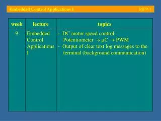
Controller #1(PID) Sensor(Magnetics) Actuator (PSU) Sensor(Magnetics) WaveformGenerator #1 Tokamak Actuator (Power Suplies) DATAACQUISITIONSYSTEM Sensor(Pressure/Interferometry) Tokamak: Actuator (Gas Puffing) Controller #2(PID) Actuator (Gas Puffing) Actuator Y Sensor X Controller #(PID) Sensor(Interferometry) WaveformGenerator #2 The control system • “Trial-and-error” type operation • Hard to get similar discharges, as the plasma is a multivariable complex system • Reprogram of waveforms is normally an empiric and lengthy task • Data acquired needs to be correlated manually against control waveforms • Single-Input Single-Output (SISO) ANALOG controllers • Not easily Re-configurable • Hard to Optimize • Allows only simple control schemes (e.g PID) • Control of Plasma Parameters are NOT coupled!
Sensors Actuators Control Unit System Components Symposium on Plasma Physics and Technology
Processing unit • 8 Analog channels • Galvanic isolated • 2 MSample/s • 14-bit • 512 MB SDRAM • DSP • FPGA • HS Serial connections • PCI bus
EP2 VS Shape & Current Control (PPCC) PF Coils Magnetics VUV impurities GAS + Pellets Interferom/Polarim Vis Da, Brem, ELM NBI Neutron X-ray etc. Vis H/D/T plasma ICRH ECE Te (R) Confinement q profile LHCD CXS Ti (R) Flux surfaces EQX TAE / EFCC LIDAR Ne&Te(R) Wall Load MSE pitch (R) EQX kinetic map Simulink code Coil Protection X-ray Ti (0) R-T Controller Rob Felton - RTMC Workshop R-T Signal Server Comms network ATM, some analogue Sensors & actuators @ JET
Computer Architectures • Harvard architecture (/von Neumann) • RISC(PIC, IBM Power PC) / CISC (80x86) • Clocking, instruction pipelining, 14 bit instruction set
PIC architecture • Single chip: • CPU • Memory • RAM • PROM/ EEPROM • oscillator • timers • watchdog • I/O • Digital • ADCs • Communications
PICs • Code efficiency - 8 bit /Harvard • Conventional Microcontrollers -1 internal bus (Z80) • Safety coding • 12, 14 or 24 bit “program memory word” • Jumps to data area impossible • Instruction Set • 33 instruction (MID range) • Single instruction cycle (=4 clock cycles); /CALL, GOTO, bit test (BTFSS, INCFSZ) • Speed (2x 386 SX 33MHz)
PICs (cont.) • Static Operation – registers are kept valid during STOP (Sleep – 1uA sink current) • Current driver • I/O pin: sink 25mA or 100mA (total) • LEDs and triacs • Several series options • Speed, thermal • Casing (sizes) • I/O, timers, serial comms, A/D • memory
DSP • 40 bit ALU • 2x40 bit accumulators • 1x40 bit bidirectional shifter • Barrel shift -15 bits right, 16 bits left • Integers vs float
Terminology • Microcontroller (sw relevancy) • I/O (external world) • Software (information) • Bugs • Programming language (ASM, C) • Hardware • Microprocessor • Memory • Interface and signal conditional circuits • Power supply (digital, analog and programming ground and shielding)
CPU Data Memory Program Memory DSP Engine Interrupts I/O Ports Timers Input Capture Module Output Compare Module Quadrature Encoder Interface (QEI) 10-bit A/D Converter 12-bit A/D Converter UART Module SPITM Module I2CTM Module Data Converter Interface (DCI) Module CAN Module dsPIC30F
Harvard • Independent Buses • Instructions are bigger than1 byte (Program memory) • Program memory: • Optimized • Single word instruction per cycle • In one jump an instruction is always executed • /von Neuman instructions with several bytes
Harvard Architecture • pipeline • 2 stages instruction execution • fetch and execution in a single cycle • Each instruction is autonomous • Every data included • No more program data access • 4 clock per instruction cycle
Instruction format • Word or byte-oriented • Bit-oriented • Literal • DSP operations • Control operations • OpCode • Variable number of bits • 2^6=64 (app. 35 instructions)
Instruction format dsPIC30F Mid-range PICs (14 bit)
Memory organization • Registers and static memory • Work register • Mid->dsPIC • File registers~RAM • General Purpose Registers (GPRs) • Special Function Registers (SPRs) • Memory banks • Limitation due to adress bits • Selection bits (avaiable trough STATUS)
Special Function Registers • Base Architecture • Reserved names • INTCON, TMR0, STATUS • R/W and read only • Some registers do not exist physically • Some registers are copied among bank memory • STATUS, FSR, INDF • Including GPR (0x70 a 0x7F) • PORTB (Banks 0 e 2) • Power ON/Reset
General Purpose Registers • User defined • Wide implementation • Indirect adress • pointers • Easy incrementation or decrementation • INDF (0x00) provide adress copy of FSR • ie changing INDF data at that adress is changed INDF(=*FSR) • de-referencing • Address: 100 102 104 106 • Variable: i j k ptr • Content: 3 5 -1 102 • int i, j, k; • int *ptr;
Example • STATUS
Interruptions and I/O • Communication between microcontroller and external world • Multi-functional digital output • Communication protocol • ADCs e DACs • Events monitoring
I/O - Port • TRISx: Data Direction register • PORTx: I/O Port register • LATx: I/O Latch register • C options in TRISx • Quick & simple • Slow & secure
Change Notification (CN) Pins • Weak pull-up (current source) • Avoiding external resistores • Originate interruptions • Change in pin states • 24 pins avaiable
Interruptions • vs Polling (attention) • Quick response to events • Peripherics • Driven actions • After taken action continues previous process • Maskable/non-maskable • Variable saving (PC e Stack) • Quick execution
INT Pin Interrupt (external interrupt) TMR0 Overflow Interrupt PORTB Change Interrupt Comparator Change Interrupt Parallel Slave Port Interrupt USART Interrupts Receive and Transmit Interrupt (CAN) A/D Conversion Complete Interrupt LVD Interrupt Data EEPROM Write Complete Interrupt Timer Overflow Interrupt CCP Interrupt SSP Interrupt Interruptions (cont.)
Communications • Serial • Synchronous • I2C • SPI • Asynchronous • RS232, RS485, RS422 (RS232 differential) • Point to point • Point/multi-point • USB, SSP • CAN • Parallel
Serial Communications • Start bits - Always 1 bit • Stop bits – 1, 1.5 ou 2 bits • Data bits - 7 ou 8 bits • Parity bits • none - no error detection • odd or even - error detection required • 1 bit added to give bit summing odd or even • CheckSum: redundancy check • CRC (cyclic redundancy check)
HandShaking • Data Terminal Ready • Data Set Ready • Clear to Send • Request To Send • Transmit Data • Receive Data • Ring • Data Carriage Detected • Ground RTS Data Terminal Equipment - Data Comunication Equipment
USART/UART • Universal Synchronous/Asynchronous Receiver Transmiter • Shift register • SYN (0b01000010)
I2C • Two bidirectional “open-drain lines” • Serial Data (SDA) • Clock (SCL) • “Pull-up” – resistor ~k • Multi-master • Master node — clock controller • Slave node — all others
I2C • 7-bit address space (10-bit addressing) • 16 reserved addresses (max 112 nodes) • Vel. • Normal - 100 kbit/s (standard mode) • Low-speed mode - 10 kbit/s (até DC) • Fast - 400 kbit/s (Fast mode) or 1 Mbit/s (Fast mode plus or Fm+), 3.4 Mbit/s High Speed mode • Max. bus capacity - 400 pF.
SPI • Operation modes • 8-bit and 16-bit Data Transmission/Reception • Master e Slave • Framed SPI Modes • Operation: 8-bit vs. 16-bit
SPI • Ideal for single-master/single-slave • Single-master bus • Do not have slave acknowledgment ! • Full duplex • 1-10Mbit • Dual-Shift register
Oscillator • Oscillator modes ( default clock source) • EC External Clock • ECIO External Clock with IO pin enabled • LP Low Frequency (Power) Crystal • XT Crystal/Resonator • HS High Speed Crystal/Resonator • RC External Resistor/Capacitor • RCIO External Resistor/Capacitor with IO pin enabled • HS4 High Speed Crystal/Resonator with 4x frequency PLL multiplier enabled
Inverter gain (mode) Frequency (power) Crystal (precision) Wake-up (frequency, noise, sleep wake-up) Oscillator Modes
PLL • Advantages PLL • EMI • SW program. • Structure • VCO • Divider • Comparator
Timers (dsPIC) • Timer 1