Download
1 / 18

E N D
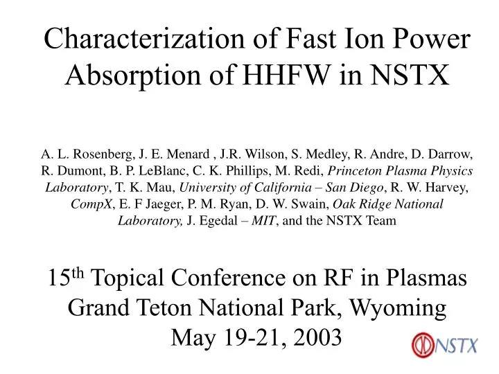
Characterization of Fast Ion Power Absorption of HHFW in NSTXA. L. Rosenberg, J. E. Menard , J.R. Wilson, S. Medley, R. Andre, D. Darrow, R. Dumont, B. P. LeBlanc, C. K. Phillips, M. Redi, Princeton Plasma Physics Laboratory, T. K. Mau, University of California – San Diego, R. W. Harvey, CompX, E. F Jaeger, P. M. Ryan, D. W. Swain, Oak Ridge National Laboratory, J. Egedal – MIT, and the NSTX Team15th Topical Conference on RF in PlasmasGrand Teton National Park, WyomingMay 19-21, 2003
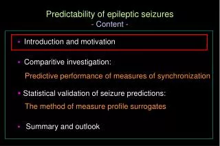
Introduction and Motivation • Ion absorption critically important to assessing viability of HHFW to heat and drive current in STs • Experimental evidence of HHFW interaction with NBI • Neutral Particle Analyzer (NPA) scannable at midplane • neutron rates, Fast Lost Ion probes • Thompson scattering measures Te, ne profiles • X-ray Crystal Spectroscopy measures peak Ti • Computational evidence • HPRT, TRANSP, CURRAY, AORSA, METS
NSTX Utilizes the TFTR ICRF system • 30 MHz Frequency corresponds to w/WD = 9-13 • 6 MW from 6 Transmitters for up to 5 s • 12 Element antenna with active phase control allows wide variety of wave spectra • k|| = ± 3-14 m-1
HHFW 12 element antenna array B • Antenna takes up almost 90° toroidally • Provides high power capability with good spectral selectivity
Phase Feedback Control Configuration RF Power Sources P5 P6 P1 P2 P3 P4 Decoupler Elements D6 p Cube Voltages V1 V2 V3 V4 V5 V6 D1 D2 D3 D4 D5 p p p p p 5 Port Cubes 1 2 3 4 5 6 7 8 10 11 9 12 I1 I7 DfV21 Antennas • Digital based phase feedback control is used to set the phase between the voltages • of antenna elements 1 through 6 • Decouplers compensate for large mutual coupling between elements and facilitate • phase control
12 10 8 ln (flux / Energy1/2) 6 4 2 80 120 100 60 140 40 20 Energy (keV) HHFW can generate a fast ion tail with NBI • D+ tail extends to 130 keV • Tail saturates in time during HHFW • Typical shot 108251 ne beam injection energy Te(0) at RF end +10 ms +20 ms Ip RF 2.4 noise level NBI 1.6 MW • Tail decays on collisional time scale
HHFW enhances neutron rate Measured RF vs. no RF RF No RF 105908 105906 RF Measurement Measurement no RF HHFW TRANSP TRANSP NBI • After RF turnoff, rate decays close to measured and predicted no RF value • TRANSP neutron rate predictions without RF input fall shorter than measured rate for RF shot
12 10 8 ln (flux / Energy1/2) 6 NPA 4 HHFW NBI 2 80 120 100 60 140 40 20 Energy (keV) Tail reduced with lower B-field, higher t B0=4.5 kG B0=4.0 kG B0=3.5 kG B0=4.5 kG B0=4.0 kG B0=3.5 kG beam injection energy • Larger t promotes greater off-axis electron absorption • Reduces fraction of power available to core fast ion population
Ion loss with lower B-field can’t account for reduction in tail • Two codes used to check ion loss at B0=4.5 kG vs. 3.5 kG for 80-120 keV ions • CONBEAM – Egedal (MIT-PSFC) • Loss fraction at 120 keV B0 = 4.5 kG: 21% • EIGOL – Darrow (PPPL) • Loss fraction at 120 keV B0 = 4.5 kG: 17% • Small change in loss fraction insignificant compared to major tail reduction • More likely an RF effect B0 = 3.5 kG: 25% B0 = 3.5 kG: 23%
k|| has little observed effect on fast ions 12 k||=14 m-1 k||=10.5 m-1 k||=7 m-1 No RF k||=14 m-1 k||=10.5 m-1 k||=7 m-1 No RF 10 8 ln (flux / Energy1/2) 6 NPA beam injection energy 4 HHFW NBI 2 80 120 100 60 140 40 20 Energy (keV) • Greater ion absorption predicted with lower k||, but surprisingly little variation in tail, small neutron enhancement with higher k||
Ray tracing predicts fast ion absorption competitive with electrons • HPRT computes hot plasma absorption over cold ion/hot electron ray path • 25-50 rays used • TRANSP output used as input for fast ion temp and density distribution • Fast ions dominate central absorption, electrons further off-axis • Ti,th = 2 Te (XCS), no thermal ion absorption Shot 105908 Time 195 ms ne0 = 3.2 1013 cm-3 nb0 = 2.5 1012 cm-3 Te0 = .6 keV Tb0 = 17.3 keV Pe=55% Pb=45% Dbeam e- r/a p
Effective Maxwellian a good approximation for fast ions Shot 108251 Time 235 ms r/a=3% TRANSP fast ion dist. fcn. One effective Maxwellian 8 Maxwellians • One effective Maxellian, exactly matching TRANSP energy density and temp., fits f(E) well, though neutron rate off +20% • More Maxwellians (including negative) can match all moments
Observation of less fast ion absorption at higher t consistent with theory t=5%, B0=4.5 kG t=9%, B0=3.5 kG Pe=62% Pb=37% Pe=73% Pb=24% e- e- Dbeam Dbeam r/a r/a • Lower on-axis absorption for lower B, higher t predicted
HPRT Power Absorption • Energy moment of Vlasov eq. + vector identities leads to [Menard, RF 1999]: • The first non-vanishing terms of this are: • Kinetic flux term is necessary if one uses the full hot, complex dielectric tensor
Clarifying Kinetic Flux • In Stix (4-15) • In Stix (4-17,19) • 1st important note – Stix, p. 75: “In expression for T, the dot products are between E*and h, and h and E.” • So, unambiguous Tis: • Does (4-15) = (4-17)? Yes! However…
Only ∙T is unique also equals: • So expression for T is not unique; only ∙T well-defined • Common loss-free plasma approximation of group velocity: is invalid, as is any expression which uses T in this form. • 2nd important note: • RHS gets wrong cross derivatives wrt k
NPA scan indicates induced tail well off-axis NPA at r/a = .02 NPA at r/a = .14 NPA at r/a = .36 beam injection energy • Depletion in particle flux with NPA Rtan further off-axis • Tail extends to same energy range • Future: scan over wider range of r/a
Summary • Clear RF-induced fast ion tail observed with NBI • Neutron rate and modeling support interaction • Good agreement between HPRT, AORSA, CURRAY • Tail formation suppressed with higher t • Little effect with k|| observed • Effective Maxwellians can represent fast ion f(E) • Kinetic flux clarified