Download
1 / 12
120 likes | 609 Views
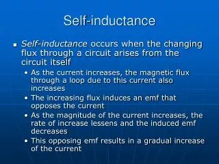
Internal inductance versus external inductance Example. Magnetic-Head Connector (MHC) Configuration of high speed magnetic head connector. Simulation only demonstrates current distribution in ground plane and in the two circular wires at 1 GHz.

E N D
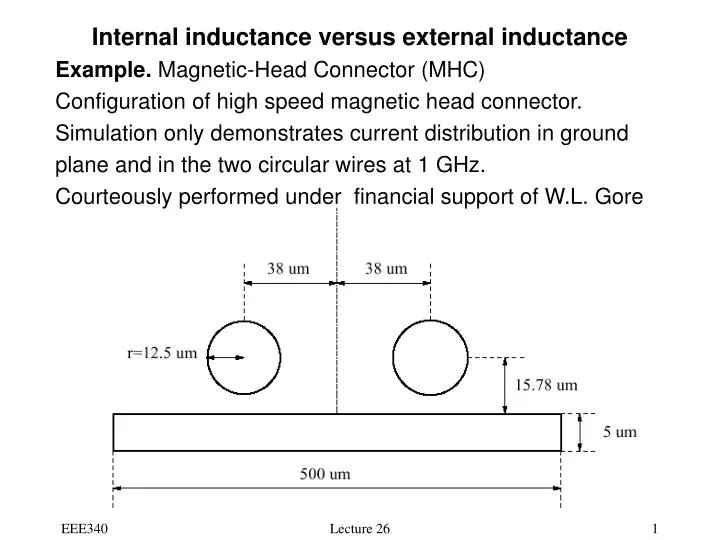
Internal inductance versus external inductance • Example. Magnetic-Head Connector (MHC) • Configuration of high speed magnetic head connector. • Simulation only demonstrates current distribution in ground • plane and in the two circular wires at 1 GHz. • Courteously performed under financial support of W.L. Gore Lecture 26
Current distribution in the ground plane Lecture 26
Magnetic Head Connector - 3 Fig. 6: Current distribution in the left and right circular wire Lecture 26
Measurement and simulation Results for MHC • Measurements from 1 MHz to 1 GHz Fig. 9: Self and mutual resistances, R11, R12 by different methods Lecture 26
Measurement and Simulation Results Self and mutual resistances, L11, L12 by different methods Quasi-static error may exceed 300%!! Lecture 26
6-12: Magnetic Energy • Consider a single closed loop of inductance L1 without initial current. • The work done by the field (to establish magnetic fields) is • W1 is the stored magnetic energy. (6.157) (6.158) Lecture 26
For a two-loop system, V21 • Similarly, • The total energy (6.159) (6.160) (6.161) Lecture 26
Generalizing the result to a system of n loops carrying currents I1, I2, …, In • where (6.162) (6.166) Lecture 26
6-12.1: Magnetic energy in terms of fields • Using • The magnetic energy (6.166) becomes • where • As (6.167) (6.169) Lecture 26
From vector identities, we can obtain • where the integrand is magnetic energy density, • From the stored magnetic energy one can evaluate the • Inductance of a system/circuit: (6-172) (6-174) (6-175) Lecture 26
l2 l1 • Example 6-18 Mutual inductance. Two coils of N1 and N2 • terns are wound on a cylinder core of radius a and • permeability The windings are of lengths • Find the mutual inductance. • Solution. • The magnetic flux b a Lecture 26
Since coil 2 has N2 turns, we have the linkage • The magnetic coupling coefficient • The best coupling is k=1 of no leakage flux (a=b, l1=l2) (6-151) (6-135) Lecture 26