Download
1 / 26
310 likes | 517 Views
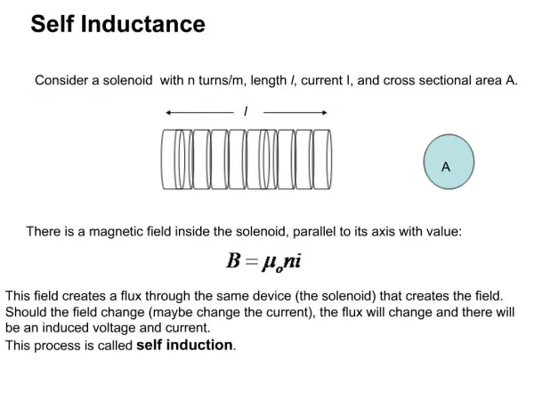
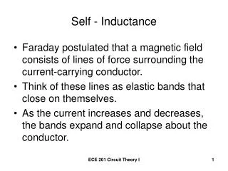
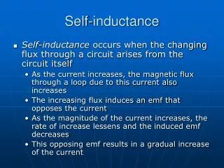
Self-Inductance. When the switch is closed, the current does not immediately reach its maximum value Faraday’s law can be used to describe the effect. Self-induced emf. A current in the coil produces a magnetic field directed toward the left (a)

E N D
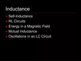
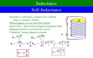
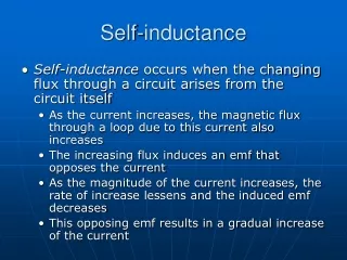
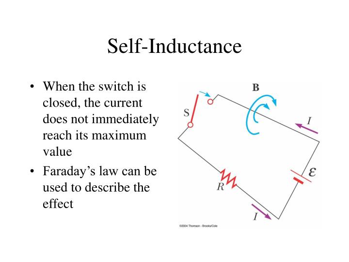
Self-Inductance • When the switch is closed, the current does not immediately reach its maximum value • Faraday’s law can be used to describe the effect
Self-induced emf • A current in the coil produces a magnetic field directed toward the left (a) • If the current increases, the increasing flux creates an induced emf of the polarity shown (b) • The polarity of the induced emf reverses if the current decreases (c)
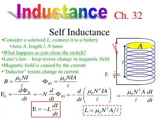
Self Inductance Define: Self Inductance
Inductance of a Solenoid • The magnetic flux through each turn is • Therefore, the inductance is • This shows that L depends on the geometry of the object
3. A 2.00-H inductor carries a steady current of 0.500 A. When the switch in the circuit is opened, the current is effectively zero after 10.0 ms. What is the average induced emf in the inductor during this time? 5. A 10.0-mH inductor carries a current I = Imax sin ωt, with Imax = 5.00 A and ω/2π = 60.0 Hz. What is the back emf as a function of time? 7. An inductor in the form of a solenoid contains 420 turns, is 16.0 cm in length, and has a cross-sectional area of 3.00 cm2. What uniform rate of decrease of current through the inductor induces an emf of 175 μV?
LR Circuits Charging Kirchhoff Loop Equation: Solution:
LR Circuits Discharging Kirchhoff Loop Equation: Solution:
Active Figure 32.3 (SLIDESHOW MODE ONLY)
14. Calculate the resistance in an RL circuit in which L = 2.50 H and the current increases to 90.0% of its final value in 3.00 s. 20. A 12.0-V battery is connected in series with a resistor and an inductor. The circuit has a time constant of 500 μs, and the maximum current is 200 mA. What is the value of the inductance? 24. A series RL circuit with L = 3.00 H and a series RC circuit with C = 3.00 μF have equal time constants. If the two circuits contain the same resistance R, (a) what is the value of R and (b) what is the time constant?
Energy in a coil PE in an Inductor PE in an Capacitor
Energy Density in a coil PE in an Inductor
31. An air-core solenoid with 68 turns is 8.00 cm long and has a diameter of 1.20 cm. How much energy is stored in its magnetic field when it carries a current of 0.770 A? 33. On a clear day at a certain location, a 100-V/m vertical electric field exists near the Earth’s surface. At the same place, the Earth’s magnetic field has a magnitude of 0.500 × 10⁻⁴ T. Compute the energy densities of the two fields. 36. A 10.0-V battery, a 5.00-Ω resistor, and a 10.0-H inductor are connected in series. After the current in the circuit has reached its maximum value, calculate (a) the power being supplied by the battery, (b) the power being delivered to the resistor, (c) the power being delivered to the inductor, and (d) the energy stored in the magnetic field of the inductor.
Example 32-5: The Coaxial Cable • Calculate L for the cable • The total flux is • Therefore, L is • The total energy is
LC Circuits Solution: Kirchhoff Loop Equation:
Active Figure 32.17 (SLIDESHOW MODE ONLY)
LRC Circuits Kirchhoff Loop Equation: Solution:
Damped RLC Circuit • The maximum value of Q decreases after each oscillation • R < RC • This is analogous to the amplitude of a damped spring-mass system
Active Figure 32.21 (SLIDESHOW MODE ONLY)
LRC Circuits • Underdamped • Critically Damped • Overdamped
41. An emf of 96.0 mV is induced in the windings of a coil when the current in a nearby coil is increasing at the rate of 1.20 A/s. What is the mutual inductance of the two coils? 49. A fixed inductance L = 1.05 μH is used in series with a variable capacitor in the tuning section of a radiotelephone on a ship. What capacitance tunes the circuit to the signal from a transmitter broadcasting at 6.30 MHz? 55. Consider an LC circuit in which L = 500 mH and C = 0.100 μF. (a) What is the resonance frequency ω0? (b) If a resistance of 1.00 kΩ is introduced into this circuit, what is the frequency of the (damped) oscillations? (c) What is the percent difference between the two frequencies?
LC Demo R = 10 W C = 2.5 mF L = 850 mH • Calculate period • What if we change • C = 10 mF • Underdamped? • How can we change damping?