Download
1 / 48
480 likes | 587 Views
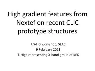
Nextef results. CLIC09, Oct. 12-16 T. Higo (KEK). Contents . Quadrant high gradient test status Initial processing and power limit VAC characteristics with Q-mass Dark current BD position Light emission Change in T18 by high gradient processing RF Optical inspection Nextef plan.

E N D
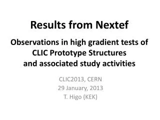
Nextef results CLIC09, Oct. 12-16 T. Higo (KEK)
Contents • Quadrant high gradient test status • Initial processing and power limit • VAC characteristics with Q-mass • Dark current • BD position • Light emission • Change in T18 by high gradient processing • RF • Optical inspection • Nextef plan CLIC09 Higo
Quad #5 status and near future plan CLIC09 Higo
So-called 9MW run Red=power (arbitrary unit) Blue = Chamber vacuum [Pa] So-called 10MW run Higher target Target = 15MW CLIC09 Higo
Gradient limit at 50ns So-called 9MW run Higher target So-called 10MW run Hard limit at 19MW, 59MV/m, 50ns CLIC09 Higo
Run11 with higher target at 113ns Powers at breakdown with 113ns pulse width for 60 hours Hard limit at 14MW for 113ns pulse CLIC09 Higo
ACC-IN pulse at hard limit Tp(ns) 51 113 Power (MW) 1914 Ea (MV/m) 5950 Sqrt(Tp)*Power 135147 Limit at similar pulse heating temperature, but more precise comparison is needed. CLIC09 Higo
Vacuum characteristics • Vacuum total pressure • Base pressure at <10-6Pa • Typically processing below 10-5Pa • Increases every time at few to 5MW range if after RF-OFF for more than several hours • Mass spectrum • M=2, 28 and 44 increase with RF-ON, but not M=18 • Especially when reaching power limit • M=2 becomes dominant residual gas after an hour or so run • M=27 and 28 change in a similar manner as time, indicating hydrocarbon-origin surface contamination CLIC09 Higo
First and Second QMA observations.Check QMA vacuum. QMA-Acc Chamber valve closed. Large Peak at M=18 (Water). Need more Q mass baking. 090918 All peaks are lowered. After Q mass baked (200deg, 2.5days). 2 28 090924 32 44 CLIC09 Higo
First QMA observation with RF OFF.QMA- ACC Chamber valve opened. Peak at M=2 (H2) largest. Water (18) becomes moderate. Others are M=28 (CO) and 44(CO2). 090924 CLIC09 Higo
QMS (1) :RF Power and gases Pressure of H2 dominated. Pressure of water is inactive. RF Power into Acc 2 18 28 ACC Chamber CCG 44 CLIC09 Higo
QMS (2): Cu and Zr BD No signal of Cu(M=63) nor Zr (M=89) . Power Acc In Acc Chamber CCG CLIC09 Higo
Breakdown pulse analysis CLIC09 Higo
Timing distribution for change>2000 CLIC09 Higo
T18 structure Function F[z] Use time difference Rs(rise)-Tr(fall) to calculate BD position. Function F(z) is calculated from design vg(z). CLIC09 Higo
Pick up large Rs, Tr change with 50ns Sampling cut at 448 Sampling cut at 448 Cut at 1000 or 2000 for timing analysis from next page. CLIC09 Higo
Breakdown cell distribution >1000 50ns higher target run 713 events were analyzed out of 1919 INTLK. CLIC09 Higo
Breakdown cell distribution >2000 50ns higher target run Mostly downstream half. Simply increasing toward output end. Indication of BD following some field gradient. 534 events were analyzed out of 1919 INTLK. CLIC09 Higo
BD position of run11 113ns, MW 113ns higher target run It is evident that there is difference than 50ns. Not increasing toward output side. Need to check the peak at cell#0. Need to check those outside structure cell region. 2000 CLIC09 Higo
Quad dark current much larger than T18 Quad T18 (Note: Power is just the value in the control program panel. Read 12MW as 19MW, though relative comparison between quad and T18_disk is OK without this.) CLIC09 Higo
Spectrum peak at very low energy T18_Disk Peaks at 8MeV/c and 4MeV/c with 108MV/m Present quad Peak at 1.2MeV/c with 19MW 59MV/m CLIC09 Higo
Possible cause of high dark currentField enhancement due to round chamfer • Simulation of field enhancement • 1.4 ~ 1.6 at radius • with gap<radius/5, step<radius/2.5 • Only a few tool passes • to shape 50 micron radius • with radius tool of 2mm • If three passed tangential discontinuity by about 30 degree • Can be relaxed by such as EP in future CLIC09 Higo
Electric field enhancement in a shallow channel with round chamfer Calculation done by T. Abe by CST MS. Waveguide field. CLIC09 Higo
Other monitors for quad PM Mirror + camera AM PM Quad Qmass FC-Mid FC-UP Camera FC-DN CLIC09 Higo
Light emission observed by usual camera • From side window • Can see several cells near center of structure • Found some BD events with a light emission from a particular cell • View from upstream beam axis • Found a light emission • Pattern interpretation is not straightforward • Some event showed bright spot smaller than cell size • Need better optical setup • Time gating, wider view, space resolution, etc. CLIC09 Higo
Possible future program for quad #5 • NEG installation in progress in this week • Further run • Longer pulse run at 173ns • Evolution of dark current • Finish high gradient and -- • RF check • Mechanical check • Optical inspection • SEM at CERN? • Further treatment? • EP ? • Further high gradient test • Improved optical inspection • Change in dark current • Possibly higher field? • These become good lessons for us to understand breakdown phenomena. CLIC09 Higo
Change in T18 through high gradient test? CLIC09 Higo
Whole history of processing of T18_VG2.4_Disk #2 CLIC09 Higo
RF check setup CLIC09 Higo
Input match not changed CLIC09 Higo
Bead pull raw data on Sep. 23 CLIC09 Higo
Bead pull amplitude plot 11422MHz Correspond to ripple of +-4% in Ea at output end. Which was not before test. Output side Input side CLIC09 Higo
Output match some change Speculation: Reflection changed around 11424MHzby G=0.05 level?? Can be source of field staggering CLIC09 Higo
Bead pull feeding from output side Output side Input side CLIC09 Higo
Phase advance per cell Condition at 22.7degC in Nitrogen Bead pull result: 11423.2MHz 120deg/cell delF 22.7 30C -1.38MHz delF N2 VAC +3.12 delF string no string +0.2MHz Total delF = 1.94MHz The structure now shows 120deg/cell at 11425.1MHz Changed by 1.1MHz through high gradient test!?!? Should confirm carefully with SLAC tuning result. CLIC09 Higo
View direction 45deg f4.1mm View area 60deg Focus within 5mm to infinity CLIC09 Higo
98 60.3 101 127.4 79 110 118.6 71 CLIC09 Higo 60.9
Optical inspection upstream Up WG direct. Beam axis Match cell March Iris Iris #2 Iris #1 60.3mm Input coupler to cylindrical TM01 line Insertion 98.0mm for observing Iris #2. This is the best we can now, only the forward iris at an enough distance. CLIC09 Higo
Optical inspection upstream and middle Insertion 98.0mm Iris #2 at first regular cell Insertion 82.7mm Iris #1 at match cell 170.9mm Iris #10 161.9mm Iris #9 CLIC09 Higo
Optical inspection downstream end 252.2mm Iris #19 Down side iris of last regular cell 243.2mm Iris #18 Upside iris of last regular cell 261.3mm Last regular cell iris #20 CLIC09 Higo
Optical inspection result and future • No significant variation was observed • Comparing input to output but • Need to inspect with better resolution • Change to straight bore scope? • Adjust focal plane? • Should be improved CLIC09 Higo
T18_Disk_#2 after high gradient test tentative conclusion • RF evaluated after high gradient test. • Input matching was kept. • Output matching changed by G=0.05 level. • Average frequency increased by 1.1MHz. • Field ripple±4.4% near output end. • Some change in RF performance was observed. • Need to compare carefully with SLAC data. CLIC09 Higo
Summary and next plan • Quad • Similar performance as quads tested at SLAC • More test in a few weeks • Inspection and think about the further test • T18 • Measurable change was observed • We need to remind this • Next plan • TD18 is top priority • Then T24_Disk, TD24_Disk before CDR • followed by T18_Disk#4, …… CLIC09 Higo
Nextef Planning revised as of CLIC09 2009 2010 2011 9 10 11 12 1 2 3 4 5 6 7 8 9 10 11 12 1 2 TD18_Quad #5 TD24_Disk #? TD18_Disk #3 T18_Disk #4 A T24_Disk #? ?? PC test PC test and system construction Nextef B construction? B X-band studies C-band Structure Test ???? Construction to shield-B NWG Cu-005 Load, WGValve KT-1 PPM6b Component, etc. tests or serving shield-B CLIC09 Higo
Nextef Configuration Nextef X-band KT-1 X-band B A KT-2 C-band CLIC09 Higo
Conclusion • Nextef will run fully dedicated for the feasibility study of CLIC 100MV/m • Nextef will boost peak power and high power stability by introducing pulse compression system • We try to construct a test area in addition to Nextef for key studies CLIC09 Higo