Download
1 / 58
580 likes | 1.03k Views
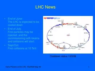
News from the LHC. J örg Wenninger Beams Department Operations group. CMS Meeting. LHC beam commissioning. S34 incident and consequences. December 2008. Part I Beam !. Beam Commissioning Phases 1 to 3. Pre-10.09.2008 beam tests : code name ‘synchronization tests’

E N D
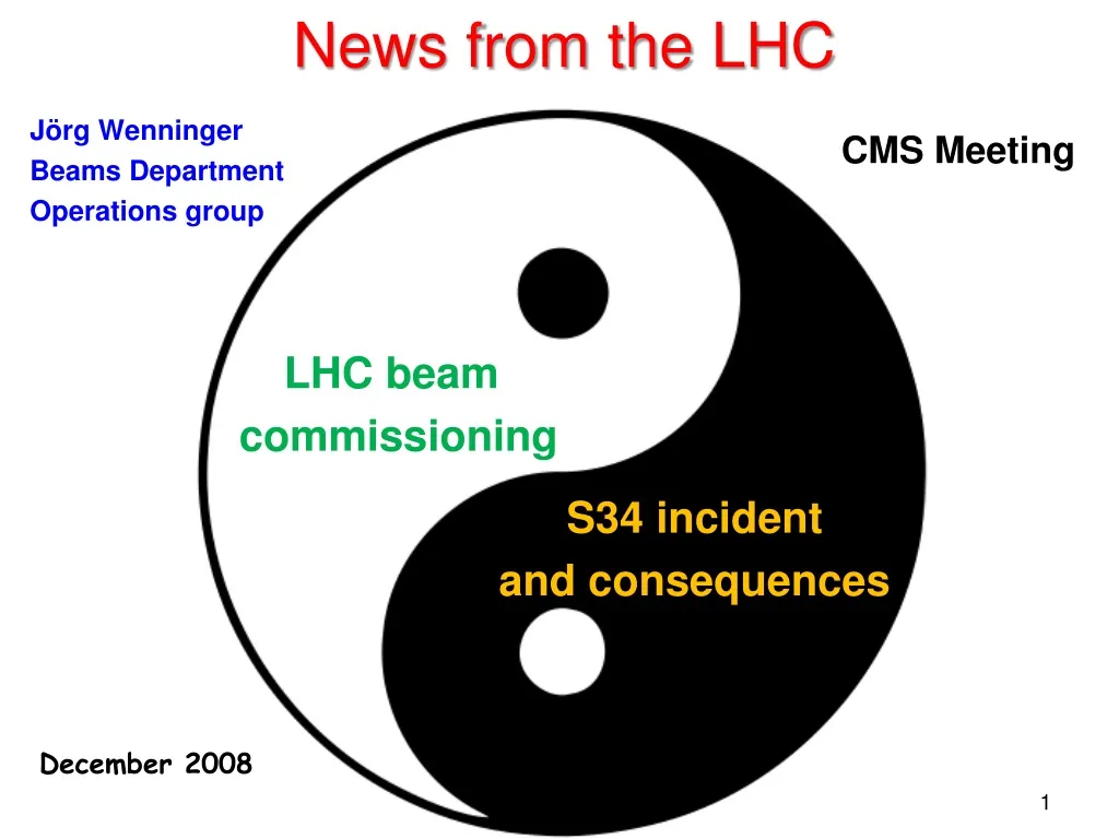
News from the LHC JörgWenninger Beams Department Operations group CMS Meeting LHC beam commissioning S34 incident and consequences December 2008
Beam Commissioning Phases 1 to 3 • Pre-10.09.2008 beam tests : code name ‘synchronization tests’ • Commission the injection elements of the LHC. • Commission controls and instrumentation of the LHC ring. • Check magnetic field (predictions), alignment and apertures. • Make sure we do not screw up too much on the 10th … • The tests were interleaved with commissioning of the remaining magnets & circuits. • Note the first time we could run all magnets together : • The evening of September 9th !!
Synch. test no. 1 8-11 August 08 Beam 2 stopped on collimator
Synch. Test no. 2 22-25 August 08 Beam 1 stopped on collimator Beam 2 stopped on collimator
Synch. Test no. 3 5-8 Sept. 08 9 Sept. 08 Beam 1 stopped on collimator Beam 2 to dump line
Polarity Errors • In single pass (trajectory) mode, focusing errors can be located by: • launching controlled trajectory oscillations • comparing the measurement with the predictions • >> Identified a number of sign errors – some rather severe (see below) ! Example of a polarity inversion of a main quadrupole (IR7). This error would have spoiled the 10th September show – very difficult to get past such an error. Histogram : measured trajectory change Points : model Polarity error Beam 2
Aperture A great relief : the aperture was very good – no buckled bellows & Co. Example for sector 78 : the aperture is probed by increasing trajectory oscillation amplitudes until losses appear. On the figures one sees the excursions of sample trajectories until losses appear.
And we quenched with beam… In the very early morning of August 9th during the first test, we provoked the first beam induced quench: BLM signal (beam1 side) BLM signal (beam2 side) • Bunch intensity ~4109 p, which is within the expected range. • >> reduced the commissioning intensity to ~2-3109 p. • In preparation of the 10th, a test revealed that even with ~2109 p one can quench • – but very unlikely in normal operation due to the large impact angle. M. Sapinski Preliminary results !
A look at the first quench : magnet perspective Voltage = 0, no resistance, magnet is superconducting. Beam impact, Voltage != 0 : resistive area in the magnet ! Voltage back to 0 – magnet has recovered spontaneously – very little energy deposition ! Voltage != 0 : protection systems enter the game and force-quench the magnet etc… 4 1 3 2 Voltage (V) across magnet 400 ms
September 10th • Despite the presence of an unbelievable crowd of people : • 10:30 : Beam 1 around the ring (in ~ 1 hour). Beam makes ~ 3 turns. • 15:00 : Beam 2 around the ring, beam makes 3-4 turns. • 22:00 : Beam 2 circulates for hundreds of turns…
Beam 2 around the ring Beam to TDI Beam to IR3 Beam to IR7 Beam to IR6 Beam to CMS
Beam2 around the ring Beam to TDI Beam to IR3 Beam to IR7 Beam to ALICE Beam to IR6 Beam to CMS
Beam2 around the ring Beam to TDI Beam to IR3 Beam to IR7 Beam to ALICE Beam to IR6 Beam to ATLAS Beam to CMS Beam to LHCb – First Turn !
First Beam Around Sept 10th 10:30 : two beam spots on a screen near ALICE indicate that the beam has made 1 turn.
Beam 2 circulating – no RF Evening of September 10th , after the crowds left : Beam 2 makes hundreds of turns after some empirical correction (no RF) • Turn by turn beam peak intensity signal at the RF position monitor. • The decay is due to the de-bunching of the beam (bunch becomes longer and longer – no RF).
Beam 2 captured by RF system Evening/Night of September 11th RF ON & tuned Beam 2 ‘captured’ RF ON – wrong frequency RF OFF RF ON – wrong phase
Beam 2 on stable closed orbit Sept 12th : Beam 2 captured, lifetime > 1 and closed orbit corrected. Looking very good… RF frequency is not (yet) correct: average hor. orbit is negative…
Electrical transformer problem… • Late evening of Friday Sept. 12th an old LEP HV transformer in point 8 failed, leading to a stop of the cryogenics – LHC ‘off’. • TS/EL had no spare (!), but a spare CMS transformer was recuperated and installed during the weekend. • Due to various other problems, the cryogenic system was only completely back for the Friday 19th. • In the meantime, access and commissioning of remaining circuits wherever cryogenics conditions were OK. • Late in the morning of Sept. 19th the last dipole circuit of sector 3-4 is commissioned to 5.5 TeV…
Status on the morning of Sept. 19th • Beam 2 well advanced: • Beam captured in RF system, good orbit and lifetimes of hours. • Optics in ‘reasonable’ shape, preparing for refinements. • Beam 1 in same state as 10th: • First turn established, beam in for 3-4 turns. • Objectives for the weekend • Bring beam 1 to same level as beam 2. • Improve measurement and correction on beam 2. • Try to circulate both beams together … • But….
And then came September 19th 11:18… • During the last commissioning step of main dipole circuit in sector 34, to 9.3kA : • At 8.7kA, development of resistive zone in the dipole bus bar between Q24.R3 and the neighboring dipole. • Most likely an electrical arc developed which punctured the helium enclosure. • Large amounts of Helium were released into the insulating vacuum. • Rapid pressure rise inside the LHC magnets • Large pressure wave travelled along the accelerator both ways. • Self actuating relief valves opened but could not handle all. • Large forces exerted on the vacuum barriers located every 2 cells. • These forces displaced several quadrupoles by up to ~50 cm. • Connections to the cryogenic line damaged in some places. • Beam ‘vacuum’ to atmospheric pressure
Dipole • 7 TeV • 8.33 T • 11850 A • 7M J
Inter-connection Vac. chamber Dipole busbar
Damage zone • Considerable collateral damage over few hundred metres • Contamination by soot and debris (magnetic !) of vacuum chambers – extends beyond mechanical damage zone. • Damage to super-insulation blankets • Large release of helium into the tunnel (6 of 15 tons) Insulating vacuum barrier every 2 cells in the arc Some moved
Collateral damage S. Myers AB depart. meeting
Intermezzo : Quench Protection • A ‚quench‘ is the phase transition from the super-conducting to a normal conducting state. • Quenches are initiated by an energy in the order of few mJ • movement of the superconductor (friction and heat dissipation), • beam losses, • cooling failures, • any other heat sources... • When part of a magnet quenches, the conductor becomes resistive, which can lead to excessive local energy deposition due to the appearance of Ohmic losses. To protect the magnet: • the quench must be detected. • the energy in the magnet /electrical circuit must be extracted. • the magnet current has to be switched off within << 1 second.
Quench Detection and Energy Discharge Power converter Dump resistor Dump resistor The quench is detected based on voltage measurements over the coils (U_mag_A, U_mag_B). The energy is distributed over the entire magnet by force-quenching with quench heaters. The power converter is switched off. The current within the quenched magnet decays in < 200 ms, circuit current now flows through the ‚bypass‘ diode that can stand the current for 100-200 s. The circuit current/energy is discharged into the dump resistors.
Dump Resistors Those large air-cooled resistors can absorb the 1 GJ stored in a dipole magnet circuit (they heat up to few hundred degrees Celsius).
Busbar Protection • The individual interconnects are not protected. • The entire busbar (i.e. all magnet interconnections of a given electrical circuit) is protected by a global protection system. In case of a busbar quench: • the power converter is switched off, • the dump resistor switch is opened to discharge the energy. • the busbar is designed to cope with the discharge time of ~ 200 s. • A look at the quench protection system data for the incident revealed that: • a busbar quench was developing, • suddenly the voltage over the busbar increased dramatically, leading to a fault of the power converter (over-voltage), • followed by the dramatic energy release (~ 200 MJ) in the cold mass. • >> Most likely cause : an electric arc due to rupture of the interconnection. • Unfortunately this is difficult to prove, since the whole dipole interconnect was ‚vaporised‘ during the event !
Busbar interconnection Interconnection resistance ~ 0.35 nW
Main Dipole / Quadrupole Interconnection Note that the connection is NOT clamped ! Splice insulation Length He II @ 1.9K, 1Bar current current • Favored hypothesis for the S34 incident cause : • Temperature increase due to an excessive resistance (estimate ~ 200 nW). • Superconductor quenches and becomes resistive at high current (temperature increase due to the resistance). • Up to a certain current, the Copper can take it (cooled by the He II). • Beyond a certain current, ‘run-away’ of the temperature, splice opens, electrical arc … Bus Bar’s Insulation Heat exchange with He II
Early Warning Signs • Following the incident, a closer look at the logged cryogenic data (temperatures and valve states) clearly indicated a heat source in the cell that was at the origin of the S34 incident: • The data revealed the presence of a ~ 200 nW resistance in that cell (before the incident): most likely the interconnect quality. • >> Logged data recorded during commissioning of the 7 other sectors was checked to locate other potential problems : a hint was found in a cell of S12. • Controlled calorimetric measurements (at different magnet currents) were started in the sectors that are still available to: • Localize cells with current dependent heat sources. • Confirm the source and localize precisely with electrical measurements.
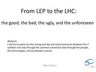
Calorimetric analysis of sectors before Sept 19 7 kA test on Sector 3-4, Sept 15th 7 kA test on Sector 2-3, April 14th DT (mk) +40 mK Temperatures stabilize Temp of Q23 keeps rising! Relative temperature, increase from 1.9 K Current in kA For comparison, another sector, identical scales 1h 9.3 kA test on Sector 1-2, Sept 1st Suspicious cell in S12 Adriaan Rijllart
Calorimetry tests : after September 19th L. Tavian 100 nW 75 nW 50 nW 25 nW S1-2 S6-7 S7-8
Calorimetry tests : candidates Not confirmed by electric measurements, poor(er) data quality L. Tavian 15R1 100 nW 75 nW 50 nW 19R1 31R6 25 nW 31R1 S1-2 S6-7 S7-8
Electrical Measurements • S12 ‘100 nW’ calorimetric anomaly: • All interconnects of the suspected cell were checked with high precision (nW) resistance measurement devices. Result: • All interconnects OK, all resistances consistent with 0.35 nW. • A systematic campaign of internal magnet resistance measurements was launched. Result: • A dipole with a 100 nW resistance was found in the suspected cell. • Test bench data indicates that this resistance was already present when the magnet was tested to 9 T/7.6 TeV. • S67 ‘50 nW’ calorimetric anomaly: • The same magnet measurements localized a dipole with a 50 nW internal resistance. • The resistance of those magnets arises from the internal interconnections! • The dipole in S12 will be exchanged, for the dipole in S67 the decision is pending…
Electrical measurements : the data The Quench Threshold is 100mV during 10ms U_1 U_2 Sampling Rate 5ms Resolution 0.125mV 13sec, 2450 points ~4mV Average = -0.88±0.02mV
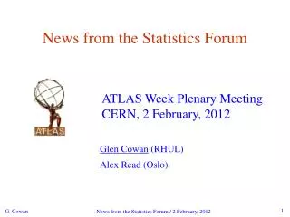
Magnet resistance measurements • Magnets are powered to different current levels. • At each step the voltage is measured to determine a possible residual resistance of splices INSIDE each magnet. • !! Does not measure the splice resistance of the tunnel interconnects !!
Voltage (V) Dipole B32.R1 with 47 nΩ splice resistance Current (A) Current (A)
Measurement campaign status • A calorimetric and electrical measurement campaign was run into December to cover the largest possible number of sectors a maximum before the start of the shutdown. • A little over ½ the LHC has been checked.
Repair • 55 magnets will be taken out by Xmas (39 dipoles, 14 SSS [quadrupole assemblies]). • Magnets will be either replaced by spares or repaired (super-insulation). • All magnets will be re-tested in SM18 before installation in sector 34. • The vacuum chambers may have to treated outside the ‘zone’ : buckled bellows and dust in beam vacuum chamber… • Estimate (preliminary) : March 09.
Consolidation : limiting pressure with flanges as relief valves Vacuum instrumentation DN100 Cryogenic inststrumentation DN63 BPM DN100 Courtesy V.Parma Beam position monitors DN100 • Each SSS/quadrupole assembly: • 4 DN100 ports (2 for vac.devices, 2 for BPM cable feedthrough) • 1DN63 port (for cryo instrumentation)
SV SV SV SV SV SV SV SV SV SV SV SV SV SV SV SV SV SV SV SV SV SV Limiting Pressure Present: 2 DN90 Consolidation optionB (A), for cold sectors: x9.3 Consolidation option C, for warm sectors: x40
Consolidation work • The following modifications and consolidations will be implemented: • Upgrade of the quench protection system for precision measurements and protection of all interconnects : early detection of similar problems + protection against symmetry quenches (already in the pipeline before S34) • Modifications of commission procedure to include cryogenic/calorimetric information and systematic electrical measurements. • Improved anchoring of SSS located at vacuum barriers. • BPM flanges modified as ‘pressure relief valves’. • Addition of pressure release valves on EVERY dipole cryostat for the warm sector. • >> E cannot be implemented for 2009 for the sectors that will be kept cold this shutdown.
Summary I • Start-up with beam: • Despite totally ,crazy’ conditions the beam start-up was excellent. • The speed of progress with beam2 exceeded even our optimistic hopes. • A lot was learned, but not enough to be sure that the rest of the early commissioning will proceed as well as the first 3 days… • Things were looking were good ! • In the operations group we are analysing what could have been done better and we are working hard to make the next start-up even more efficient !
Summary II • Sector 34 incident: • Revealed a weakness in the magnet protection system which did not cover dramatic bus-bar/interconnect incidents. • Repair or replacement of ~ 55 magnets will take most of the shutdown. • Ongoing work to analyse consequences/fix the vacuum chamber ‘pollution’ in the sector. • Search for local resistances: • Powerful calorimetric and electric measurements were validated to localize suspicious electrical resistances. • A little over half the ring could be checked. No other bad interconnect was localized, but two dipoles with internal resistances were identified: • Sector 12 / 15R1: resistance of ~ 90 nW >> dipole will be replaced. • Sector 67 / 31R6: resistance of ~ 50 nW.