Download

1 / 41
410 likes | 473 Views
News from the ILC. Barry Barish Users’ Meeting Fermilab 9-June-05. Why e + e - Collisions?. elementary particles well-defined energy, angular momentum uses full COM energy produces particles democratically can mostly fully reconstruct events. A Rich History as a Powerful Probe.

E N D
News from the ILC Barry Barish Users’ Meeting Fermilab 9-June-05
Why e+e- Collisions? • elementary particles • well-defined • energy, • angular momentum • uses full COM energy • produces particles democratically • can mostly fully reconstruct events Fermiab Users' Meeting - Barish
A Rich History as a Powerful Probe Fermiab Users' Meeting - Barish
The Energy Frontier Fermiab Users' Meeting - Barish
Why a TeV Scale? • Two parallel developments over the past few years (the science) • The precision information e+e- and n data at present energies have pointed to a low mass Higgs; Understanding electroweak symmetry breaking, whether supersymmetry or an alternative, will require precision measurements. • There are strong arguments for needing both pp and e+e- collisions to fully exploit the exciting science expected in the 1 TeV energy scale. Fermiab Users' Meeting - Barish
Why a TeV Scale e+e- Accelerator? • Two parallel developments over the past few years (the technology) • Designs and technology demonstrations have matured on two technical approaches for an e+e- collider that are well matched to our present understanding of the physics. Fermiab Users' Meeting - Barish
Which Technology to Choose? • Two alternate designs -- “warm” and “cold” had come to the stage where the show stoppers had been eliminated and the concepts were well understood. • A major step toward a new international machine required uniting behind one technology, and then working toward a unified global design based on the recommended technology. Fermiab Users' Meeting - Barish
International Technology Review Panel Fermiab Users' Meeting - Barish
Evaluate a Criteria Matrix • The panel analyzed the technology choice through studying a matrix having six general categories with specific items under each: • the scope and parameters specified by the ILCSC; • technical issues; • cost issues; • schedule issues; • physics operation issues; • and more general considerations that reflect the impact of the LC on science, technology and society Fermiab Users' Meeting - Barish
The Recommendation • We recommend that the linear collider be based on superconducting rf technology • This recommendation is made with the understanding that we are recommending a technology, not a design. We expect the final design to be developed by a team drawn from the combined warm and cold linear collider communities, taking full advantage of the experience and expertise of both(from the Executive Summary). • The superconducting technology has several very nice features for application to a linear collider. They follow in part from the low rf frequency. Fermiab Users' Meeting - Barish
The Community then Self-Organized Nov 13-15, 2004 Fermiab Users' Meeting - Barish
The First ILC Meeting at KEK Fermiab Users' Meeting - Barish
Formal organization begun at LCWS 05 at Stanford in March 2005 when I became director of the GDE The Global Design Effort Technically Driven Schedule
GDE – Near Term Plan • Staff the GDE • Administrative, Communications, Web staff • Regional Directors (each region) • Engineering/Costing Engineer (each region) • Civil Engineer (each region) • Key Experts for the GDE design staff from the world community (please give input) • Fill in missing skills (later) Total staff size about 20 FTE (2005-2006) Fermiab Users' Meeting - Barish
GDE – Near Term Plan • Schedule • Begin to define Configuration (Aug 05) • Baseline Configuration Document by end of 2005 ----------------------------------------------------------------------- • Put Baseline under Configuration Control (Jan 06) • Develop Reference Design Report by end of 2006 • Three volumes -- 1) Reference Design Report; 2) Shorter glossy version for non-experts and policy makers ; 3) Detector Concept Report Fermiab Users' Meeting - Barish
GDE – Near Term Plan • Organize the ILC effort globally • First Step --- Appoint Regional Directors within the GDE who will serve as single points of contact for each region to coordinate the program in that region. (Gerry Dugan (North America), Fumihiko Takasaki (Asia), offered to Brian Foster (Europe)) • Make Website, coordinate meetings, coordinate R&D programs, etc • R&D Program • Coordinate worldwide R & D efforts, in order to demonstrate and improve the performance, reduce the costs, attain the required reliability, etc. (Proposal Driven to GDE) Fermiab Users' Meeting - Barish
Starting Point for the GDE Superconducting RF Main Linac Fermiab Users' Meeting - Barish
Parameters for the ILC • Ecm adjustable from 200 – 500 GeV • Luminosity ∫Ldt = 500 fb-1 in 4 years • Ability to scan between 200 and 500 GeV • Energy stability and precision below 0.1% • Electron polarization of at least 80% • The machine must be upgradeable to 1 TeV Fermiab Users' Meeting - Barish
Towards the ILC Baseline Design Fermiab Users' Meeting - Barish
Specific Machine Realizations • rf bands: • L-band (TESLA) 1.3 GHz l = 3.7 cm • S-band (SLAC linac) 2.856 GHz 1.7 cm • C-band (JLC-C) 5.7 GHz 0.95 cm • X-band (NLC/GLC) 11.4 GHz 0.42 cm • (CLIC) 25-30 GHz 0.2 cm • Accelerating structure size is dictated by wavelength of the rf accelerating wave. Wakefields related to structure size; thus so is the difficulty in controlling emittance growth and final luminosity. • Bunch spacing, train length related to rf frequency • Damping ring design depends on bunch length, hence frequency Frequency dictates many of the design issues for LC Fermiab Users' Meeting - Barish
Cost Breakdown by Subsystem Civil SCRF Linac Fermiab Users' Meeting - Barish
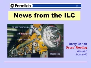
TESLA Cavity ~1m 9-cell 1.3GHz Niobium Cavity Reference design: has not been modified in 10 years Fermiab Users' Meeting - Barish
What Gradient to Choose? Fermiab Users' Meeting - Barish
Gradient Results from KEK-DESY collaboration must reduce spread (need more statistics) single-cell measurements (in nine-cell cavities) Fermiab Users' Meeting - Barish
Electro-polishing (Improve surface quality -- pioneering work done at KEK) BCP EP • Several single cell cavities at g > 40 MV/m • 4 nine-cell cavities at ~35 MV/m, one at 40 MV/m • Theoretical Limit 50 MV/m Fermiab Users' Meeting - Barish
How Costs Scale with Gradient? 35MV/m is close to optimum Japanese are still pushing for 40-45MV/m 30 MV/m would give safety margin Relative Cost Gradient MV/m C. Adolphsen (SLAC) Fermiab Users' Meeting - Barish
Fermilab - Emerging ILC SCRF Program H Carter Fermiab Users' Meeting - Barish
Fermilab ILC SCRF Program Fermiab Users' Meeting - Barish
Fermilab ILC SCRF Program Fermiab Users' Meeting - Barish
Fermilab ILC SCRF Program Fermiab Users' Meeting - Barish
Fermilab ILC SCRF Program Fermiab Users' Meeting - Barish
Fermilab ILC SCRF Program Fermiab Users' Meeting - Barish
TESLA Cavity ~1m 9-cell 1.3GHz Niobium Cavity Reference design: has not been modified in 10 years Fermiab Users' Meeting - Barish
Evolve the CavitiesMinor Enhancement Low Loss Design Modification to cavity shape reduces peak B field. (A small Hp/Eacc ratio around 35Oe/(MV/m) must be designed). This generally means a smaller bore radius Trade-offs (Electropolishing, weak cell-to-cell coupling, etc) KEK currently producing prototypes Fermiab Users' Meeting - Barish
New Cavity Design Re-entrant 28 cell Super-structure More radical concepts potentially offer greater benefits. But require time and major new infrastructure to develop. single-cell achieved45.7 MV/m Q0 ~1010 (Cornell) Fermiab Users' Meeting - Barish
ILC Siting and Civil Construction • The design is intimately tied to the features of the site • 1 tunnels or 2 tunnels? • Deep or shallow? • Laser straight linac or follow earth’s curvature in segments? • GDE ILC Design will be done to samples sites in the three regions • North American sample site will be near Fermilab Fermiab Users' Meeting - Barish
Fermilab ILC Civil Program A Fermilab Civil Group is collaborating with SLAC Engineers and soon with Japanese and European engineers to develop methods of analyzing the siting issues and comparing sites. The current effort is not intended to select a potential site, but rather to understand from the beginning how the features of sites will effect the design, performance and cost Fermiab Users' Meeting - Barish
Strawman Final Focus Fermiab Users' Meeting - Barish
Fermilab and the ILC • Fermilab is rapidly developing a superconducting RF capability for the main linac design and development for the ILC. • The Civil group at Fermilab is playing a central role in developing methods for understanding the siting and the interplay with the design. • Plans are being developed to build a strong accelerator physics group at Fermilab for the ILC. • There are many opportunities for involvement by the experimental community in the accelerator, the machine detector interfaces and the detector designs. -------------------------------------------------------------------------------------- • Fermilab can position itself very well to be able to succesfully bid to host the ILC, without mortgaging the rest of the program Fermiab Users' Meeting - Barish
Conclusions Remarkable progress in the past two years toward realizing an international linear collider: important R&D on accelerator systems definition of parameters for physics choice of technology start the global design effort funding agencies are engaged Many major hurdles remain before the ILC becomes a reality (funding, site, international organization, detailed design, …), but there is increasing momentum toward the ultimate goal --- An International Linear Collider. Fermiab Users' Meeting - Barish