Download
1 / 12
120 likes | 123 Views
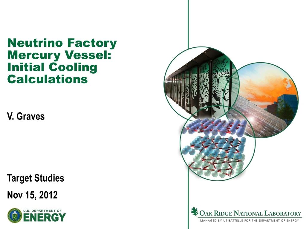
Neutrino Factory Mercury Vessel: Initial Cooling Calculations. V. Graves Target Studies Nov 15, 2012. Target System Review. Current mechanical concept incorporates independent mercury and shielding modules

E N D
Neutrino Factory Mercury Vessel:Initial Cooling Calculations V. Graves Target Studies Nov 15, 2012
Target System Review • Current mechanical concept incorporates independent mercury and shielding modules • Separates functionality, provides double mercury containment, simplifies design and remote handling • Each vessel assumed to be cooled with Helium • Shielding vessel filled with tungsten beads • Mercury vessel cooling chambers empty • Purpose: take an initial look at the cooling issues
Helium Properties @ 20C http://www.mhtl.uwaterloo.ca/old/onlinetools/airprop/airprop.html
Analysis Model Simplification • First-order cooling analysis based on simplified geometry model • Break inner and outer regions into supply/return channels of equal areas within each region Mercury Chamber Mercury Chamber Cooling Clearance Gap Not to scale Tungsten Shielding Ao total = 3.6m^2 Ai total = 0.1m^2
Helium Mass Flow Rates • Assumptions • qt = 1.5 MW • qm = 0.5 MW • ρ = 0.16674 kg/m^3 • Cp = 5193 J/kg-K • Helium ΔT <= 100C • Helium velocity <= 100 m/s qt qm 1kgHe @ STP = 6 m^3
T2K Target Design • Required flow rate 32 g/s • Minimize dP (max 0.8 bar) due to high flow rate (avg = 200 m/s)
Mercury Vessel Calculations • Mercury cooling chamber empty (only Helium) • Assume 4 cooling paths (8 chambers) • Area may be adequate, but asymmetric heating may be problem • Pressure drop through system needs to be calculated Helium Supply Channels - Blue Helium Return Channels - Red
Tungsten Shielding Vessel Calculations • Shielding vessel cooling chamber not empty (Tungsten spheres) • Assume 4 cooling paths (8 chambers) Helium Supply Channels - Green Helium Return Channels - Yellow • Area adequate, may reduce helium velocity • Pressure drop through spheres must be reviewed
Tungsten Shielding Vessel Pressure Drop • Ergun Equation gives pressure drop through fixed beds of uniformly sized solids
Pressure Drop Results • Assumptions • ε = 0.4 • dp = 1 cm • Results indicate He pressure ~180 bar required • 100m/s velocity results in large amounts of stored energy within system • Implies we need to limit He velocity to ~ 10 m/s • Requires 10X more flow area • Space is available • If need 1 s to recool the He in a heat exchanger, need 3 kg, volume = 18 m3 http://www.hep.princeton.edu/~mcdonald/mumu/ target/weggel/W&WC_spheres.pdf Module length ~ 6m
Mechanical Complexities • Non-equally distributed energy deposition • Complicated cooling channel geometries • Flow control hardware likely to increase space requirements • Implement two helium systems (one for mercury cooling, one for tungsten)?
Summary • Mercury Module now provides double-wall mercury containment with no leak path into tungsten cooling channels • Helium cooling of the mercury and shielding vessels is not straightforward • Initial calculations performed based on guesses for energy deposition and very simple geometry model