Download
1 / 12
120 likes | 245 Views
Effect of DIFFERENT QUAD CONFIGURATIONS on EMITTANCE DILUTION of USColdLC LATTICE. Kirti Ranjan Fermilab and University of Delhi, India & Nikolay Solyak and Shekhar Mishra Fermi National Accelerator Laboratory & Peter Tenenbaum Stanford Linear Accelerator Center.

E N D
Effect of DIFFERENT QUAD CONFIGURATIONS on EMITTANCE DILUTION of USColdLC LATTICE Kirti Ranjan FermilabandUniversity of Delhi, India & Nikolay Solyak and Shekhar Mishra Fermi National Accelerator Laboratory & Peter Tenenbaum Stanford Linear Accelerator Center LET MEETING, JULY 5, 2005
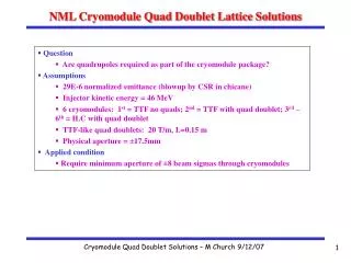
USColdLC MAIN LINAC • US Cold LC Main Linac Design • Linac Cryogenic system is divided into Cryomodules(CM), with 12 structures / CM • Magnet Optics : FODO lattice, with b phase advance of 600 in each plane • Each quad has a Cavity style BPM and a Vertical Corrector magnet; horizontally focusing quads also have a nearby Horizontal Corrector magnet. • Main Linac Design • ~11 km length • 9 Cell structures at 1.3 GHz and 12 structures per cryostat • Total structures : 7920 • Loaded Gradient : 30 MeV/m • Injection energy = 5.0 GeV • Initial Energy spread = 2.5 % • Extracted beam energy = 250.7 GeV • Beam Conditions • Bunch Charge: 2.0 x 10¹⁰ particles/bunch • Bunch length = 300 mm • Normalized injection emittance: geY= 20 nm-rad
USColdLC MAIN LINAC ab initio (Nominal) Installation Conditions • BPM transverse position is fixed, and the BPM offset is w.r.t. Cryostat • Only Single bunch used • No Jitter in position, angle etc.; No Ground Motion and Feedback • Steering is performed using Dipole Correctors.
STEERING ALGORITHM : ONE-to-ONE vs. DFS One-to-One DFS Divide linac into 7 segments • Read all Q-BPMs in a single pulse • Compute set of corrector readings and apply the correction • Constraint – minimize (zero) RMS of the BPM readings • Iterate few times before going to the next segment. • Performed for 100 Seeds Divide linac into 18 segments • Two orbits are measured • Vary energy by switching off structures in front of a segment (no variation within segment) • Measure change in orbit (fit out incoming orbit change from RF switch-off) • Apply correction • Constraint – simultaneously minimize dispersion and RMS of the BPM readings (weight ratio: ) • Iterate twice before going to the next segment • Performed for 100 Seeds
FOR USColdLC NOMINAL CONDITIONS Mean:470 nm-rad Mean:6.9 nm-rad DFS 1:1 90%:13.1 nm-rad 90%:940 nm-rad Emittance Dilution Emittance Dilution Average Normalised Emittance Growth for 100 seeds • For 1 Quad / 2CM (330 Quads; 165 F and 165 D) • No Autophasing considered • Wakefields Included (based on the calculations of Zagorodnov & Weiland 2003 • 100 seeds 1:1 Av. Normalized Emittance (nm-rad) DFS Length (m) • Lower mean emittance growth for DFS than One-to-One
Effect of varying quad spacing – 6 different configurations with diff. quad spacing (varies from 1 Quad / 1 CM to 1 Quad / 6 CM ) • Dispersion Case – Quad, BPM Offsets and Structure, CM Pitch • Wake Case – Structure, CM offset, wakefields Dispersion 1:1 Emittance dilution Wakes Number of Quads (NQ) • Projected emittance growth is dominated by dispersive sources • Large quad spacing seems to be an attractive choice
QUAD CONFIGURATIONS • Constant phase advance of 600; No Autophasing considered; Nominal Misalignment conditions; 100 seeds; 18 DFS segments; Launch region has 7 BPMs Av. Normalized Emittance (nm-rad) Length (m) Length (m)
QUAD CONFIGURATIONS Effect of No. of BPMs in Launch region (DFS Segments = 18) Effect of No. of quads per DFS segment (BPMs in Launch region = 7) Nominal DFS 1 Quad / 2CM DFS 1 Quad / 2CM Av. Normalized Emittance (nm-rad) Length (m) Length (m) • Better for larger number of quads per DFS segment (2,5,9,18 give almost comparable results) • Tuned for 7 BPMs in Launch Region for 1Q/2CM (5,7,10 give almost similar results
QUAD CONFIGURATIONS • Effect of ADDING 3 extra BPMs and COR in 1Q/4CM b/w Quads 1-2; 2-3; 3-4 Av. Normalized Emittance (nm-rad) 1:1 DFS Length (m) Length (m) • Almost no effect of adding extra BPMs / YCOR
QUAD CONFIGURATIONS • To avoid the possible systematic effects RF structure and CM Pitch : OFF Launch region BPM RMS OFFSET ~ 0 RF structure and CM Pitch : OFF DFS DFS • 1 Q / 4CM is more sensitive to RF / CM pitches
QUAD CONFIGURATIONS • Effect of varying No. of DFS segments for 1 Q / 4 CM ; Nominal misalignment; 100 seeds
QUAD CONFIGURATIONS • Initial Energy = 15 GeV (energy spread 130 MeV ); Nominal misalignment; 100 seeds