Download
1 / 22
220 likes | 386 Views
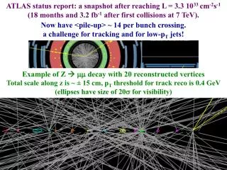
Study of Single Bunch Emittance Dilution in NLC Linac (1 TeV CM). Nikolay Solyak (Fermilab) for. Kirti Ranjan and Ashutosh Bhardwaj University of Delhi, India & Peter Tenenbaum Stanford Linear Accelerator Center & Shekhar Mishra, Fermilab. OVERVIEW. Emittance Dilution in NLC Main Linac:

E N D
Study of Single Bunch Emittance Dilution in NLC Linac(1 TeV CM) Nikolay Solyak (Fermilab) for Kirti Ranjan and Ashutosh Bhardwaj University of Delhi, India & Peter Tenenbaum Stanford Linear Accelerator Center & Shekhar Mishra, Fermilab
OVERVIEW • Emittance Dilution in NLC Main Linac: • Single Bunch Beam Break Up • Incoherent sources • Beam Based Alignment • RF Structure Alignment • Quad Alignment • Dispersion Free Steering • MATLIAR – Main Linac Simulation • Results • Conclusions / Plans
Goal: • To study single-bunch emittance dilution in NLC Main Linac for the nominal condition. • To compare the emittance dilution performance of two different steering algorithms FC and DFS for the NLC nominal conditions. • To compare the steering algorithms for conditions different from the nominal
NLC MAIN LINAC • NLC Main linac will accelerate e-/e+ from ~10 GeV -> 250 GeV, (after Upgrade 500 GeV) • There are few major design issues: • Energy: Efficient acceleration of the beams • Luminosity: Emittance preservation => Primary sources of Dilution: • Transverse Wakefields (Beam Break Up): Short and Long Range • Dispersive and Chromatic Effects • Transverse Jitter • Reliability • Vertical plane would be more challenging: • Large aspect ratio (x:y) in both spot size and emittance (~100:1) Normalized Emittance Dilution Budget in NLC Main Linac (both for 500 GeV / 1 TeV machine) DR Ext. => ML Inject. => ML Ext. =>IP Hor. (nm-rad): 3000 => 3200 => 3300 (3.3%) =>3600 Vert. (nm-rad): 20 => 24 => 34 (50%) =>40
MAIN LINAC EMITTANCE DILUTION - BEAM BREAK UP (BBU) The most severe source of emittance dilution is the BBU instability, which occurs when beam undergoes betatron oscillations in Linac. • Single-Bunch BBU • Solution: BNS Damping: Introduce correlated energy spread (RF phase): • Bunch head higher in energy than bunch tail • Multi-Bunch BBU • Solution: Damped Detuned Structure For Beam offset ~ 0.25Y ~201 % ~ 5.7 %
SINGLE BUNCH - WHAT’s LEFT AFTER BBU? • Chromatic and Dispersive Sources • Misalignments: • Beam-to-Quad offsets (most problematic) • Beam-to-RF Structure offsets • RF Structure pitch angles • Quad Roll Errors • Quad Strength • Transverse Jitter Misalignment Tolerances (Vertical plane) in NLC ML (500 GeV CM)
BEAM BASED ALIGNMENT (BBA) • Alignment tolerances can not be met by ab initio installation (~50 m.) • Quads and RF structures need to be aligned with beam-based measurements • Set of all such techniques “Beam Based Alignment (BBA)” Instrumentation • The instrumentation and control devices in the NLC design, which are relevant to the BBA and steering are: • Q-BPM in the bore of each quad, with of <1 m resolution, and a static offset BPM-to–Q offset of ~ 2 m. • Structure BPM (S-BPM) at the upstream/ downstream end of each structure ~ 5 m resolution. • A remote controlled precision magnet mover with 50 nm step size in x- and y- independently • A remote controlled precision girder mover at each end of the girder capable of moving in the x/y- direction.
BBA - RF STRUCTURE ALIGNMENT • S-BPMs: Beam position in RF structure is measured by the Amplitude and Phase of the Dipole Wakefield signal from x/y damping manifolds. • Structure Alignment: Nulling Technique. • Four structures are pre-aligned on the girder with 50 μm rms. • Consequently, an RF girder can be aligned by simply measuring the beam position at the upstream and downstream ends of each structure on the girder, fitting a straight line to the resulting measurements, and setting the girder translation stages to zero the average offset and slope of the BPM readings. • “Simple” algorithm for RF alignment (to zero mean offset /angle on S-BPMs) works if: • unexpected No systematic offsets in S-BPM reading. • Structure stays “straight” between beam-based shape measurements
BBA - QUAD ALIGNMENT • Every quad contains a captured Q-BPM • Quad alignment – How to do? • Find a set of BPM readings for which beam should pass through the exact center of every quad • Move the quads until that set is achieved and Steer the beam • Quad alignment is relatively difficult: • Moving a quad steers the beam • BPM Electrical Center ≠ Quad Magnetic Center • RMS difference ~ 100 µm (pre-alignment) • Can’t just “steer BPMs to Zero” because of the BPM – to –QUAD offset • Measure BPM-to-Quad offsets => Quad Shunting.
BBA - QUAD ALIGNMENT • Quad Shunting: Measure beam kick vs. quad strength (~20%) to determine BPM-to-Quad offset (prerequisite, routinely done monthly) • Not adequate to achieve micrometer-level accuracy • up to ~ 5μm BPM-to-Quad offset. • One of the steering Algorithm studied here is based on the quad shunting followed by Flat steering of the beam through the Quads down the Linac (called “French Curve” (FC)). • Look for a technique which does not require the knowledge of the BPM-to-Quad offset Dispersion Free Steering. • (Proposed by Raubenheimer/Ruth [NIM A302,191-208,1991])
DISPERSION FREE STEERING (DFS) • DFS is a technique that aims to directly measure and correct dispersion in a beamline. • General principle: • Measure dispersion (via mismatching the beam energy to the lattice) • Calculate correction (via steering magnets or magnet movers) needed to zero dispersion • Apply the correction • Very successful in rings (LEP, PEP, others) • Less successful at SLC (never reduced resulting emittance as much as predicted) (Note: SLC varied magnet strengths (center motion?), others varied beam energy)
SIMULATION software: MATLAB+LIAR (MATLIAR) • LIAR (LInear Accelerator Research Code) • General tool to study beam dynamics • Simulate regions with accelerator structures • Includes wakefield, dispersive and chromatic emittance dilution • Includes diagnostic and correction devices, including beam position monitors, RF pickups, dipole correctors, magnet movers, beam-based feedbacks etc • MATLAB drives the whole package allowing fast development of correction and feedback algorithms • CPU Intensive: Two Dedicated Processors for the purpose
MATLIAR SIMULATION: NLC MAIN LINAC (1 TeV CM) • Test the steering algorithm in simulation. As an initial condition, all quads, girders and rf structures are misaligned by the amount listed in Table. • 100 seeds of misalign linac were used in all the simulations. Nominal Conditions:
MATLIAR SIMULATION: NLC MAIN LINAC (1 TeV CM) • Main Linac Design • ~14.3 km length • 17856 X-band RF (11.424GHz) structures, each ~0.6 m length • 4 structures per girder • 986 Quads • Injection energy = 7.87 GeV • Initial Energy spread = 1.48 % • Extracted beam energy = 500 GeV • Beam Conditions • Bunch Charge: 0.75 x 10¹⁰ particles/bunch • Bunch length = 110 mm • Normalized injection emittance: • geX = 3000 nm-rad • geY= 20 nm-rad • Only Single bunch used • No Jitter in position, angle etc.; No Ground Motion and Feedback
STEERING ALGORITHM FRENCH CURVE (FC) vs. DFS FC Steering DFS Break linac into segments of ~ 50 quadsIn each segment: • Read all Q-BPMs in a single pulse • Using the LIAR program’s optical transport matrices, compute set of magnet moves and apply the correction • Constraint – simultaneously minimize RMS of the BPM readings and RMS movements of magnets • Move each girder’s endpoints to zero the average of the S-BPMs on that girder • Iterate a few times and go on to next segment. Next segment starts from the center quad of the previous segment (50% overlap) • Performed for 100 Seeds Break linac into segments of ~50quads in each segment: • For each segment, determine how many upstream RF structures must be switched off to vary the energy at the upstream end of the segment by 20% of the design or 35 GeV, whichever is smaller. • Switch off the necessary structures • Measure change in the BPM readings throughout the segment • Apply correction • Constraint – simultaneously minimize RMS dispersion and RMS magnet motion • Align RF structures (move girder) • Iterate each step 4 times and go on to next segment • Performed for 100 Seeds
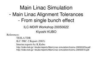
RESULTS: NOMINAL CONDITIONS Vertical (goal=50%) Horizontal (goal 3.3%) 100 seeds FC Conservative limit DFS • DFS: Lower mean emittance growth than FC. • DFS is more effective in vertical plane (which is good!)
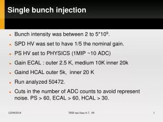
RESULTS: STRUCTURE-to-GIRDER OFFSET • gex growth in DFS and FC: • DFS: mean (~ x2.5) within tolerance. • DFS: 90% CFL can create problem. • FC: both mean and 90% limit beyond tolerance even for nominal values. Horizontal Budget (3.3%) Nominal • gey growth in FC: • remains almost constant (~ x5nominal values), but much above tolerance. Vertical • gey growth in DFS: • increases more rapidly. • mean within specs. (~x5 times) • 90% CFL can cause problem (machine should be “mean” seed !!) Budget (50%) Nominal
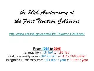
BPM-to-QUAD OFFSET Horizontal • gey & gex growth in FC: • Increases significantly • Much above tolerance. Nominal • gey & gex growth in DFS: • Increases gradually due to soft constraints and initial beam condition. • Mean is within tolerance for ~ x 2.5 nominal values. Vertical Nominal
BPM RESOLUTION Horizontal • gey & gex growth in FC: • Lesser dependence, but, • much above tolerance. Nominal Vertical • gey & gex growth in DFS: • Depends heavily on BPM resolution. • Should remain within nominal values. Nominal
NUMBER OF DFS SEGMENTS and overlapping Horizontal • gex growth in DFS: • Doesn’t depend much on the no. of segments . • gey growth in DFS: • Decreases significantly from 10-> 20, but then decreases gradually. • Nominal looks O.K. • Overlapping the segments (like in FC) doesn’t affect much. Vertical
EFFECT OF PITCH ANGLE b/w STRUCTURE & GIRDER Mean % Emittance Growth in vertical direction * RMS horizontal and vertical misalignments, yaw and pitch angles of whole structure w.r.t. Girder. • mean % gey growth in DFS • structure-to-girder pitch angle alone accounts for ~ ½ the total growth. • a serious limitation on the performance if not corrected.
SUMMARY / PLAN • Normalized emittance growth (Single bunch) in Main Linac for 1 TeV CM NLC machine is simulated using MATLIAR • DFS and FC steering algorithm are compared in terms of: • Structure-to-girder offsets • BPM-to-Quad offset • BPM resolution • Structure-to-girder pitch angle only • DFS algorithm provides significantly better results than FC. DFS results are within emittance budget for mean seeds (for Nominal conditions) • DFS algorithm is drastically affected by BPM resolution and structure-to-girder pitch angle – should remain within their nominal tolerances PLAN • Include Transverse Jitter and Ground Motion • Perform a Similar Study for TESLA LINAC