Download
1 / 30
330 likes | 662 Views
Advanced Valve Control. Submitted for MAE 442 (sec 001) Dr. Klang May 4, 2007 Chris Dirito Taylor Hobgood Dawn Glover. Outline. Valve Basics Advantages of Variable Valve Control Operation Characteristics Types of Variable Valve Control Lift Duration Phase

E N D
Advanced Valve Control Submitted for MAE 442 (sec 001) Dr. Klang May 4, 2007 Chris Dirito Taylor Hobgood Dawn Glover
Outline Valve Basics Advantages of Variable Valve Control Operation Characteristics Types of Variable Valve Control Lift Duration Phase Manufacturers and Examples Future Possibilities
Variable Valve Timeline VVT- Variable Valve Timing It can be seen that according to the trend VVT will reach ~ 90 percent of vehicles in 2010 (according to Prof. Dr. Peter Walzer)
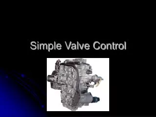
Variable Valve Introduction Why Use Variable Valve Timing and Lift? Most basic form of a push rod valvetrain is shown in the adjacent picture. This systems Valvetrain characteristics cannot be changed once the engine is started Limitations: Fuel Economy and Power are only optimized at one particular RPM, Throttle Position Broad torque curves are sacrificed
VVT Advantage It can be seen from the graph the increases in torque across the power range of the VVT engine
Variable Valve Types Valve Lift Specified Amount the Valve Opens to Allow Air and/or Fuel Air Mixture Into Combustion Chamber Controlled by Camshaft Lobe Height, Maximum at the Cam Nose Typically Specified as Height Valve “Lifts” Away From Valve Seat
Variable Valve Types • Valve Duration • Specified Time the Valve is Open • Controlled By Camshaft Profile Geometry, Length of Lobe • Measured in Degrees of Rotation, Either from Camshaft or Crankshaft
Variable Valve Types • Valve Timing • Changes Point at which Valve Opening begins with respect to crankshaft position. • Typically attained by controlling an interface between the timing belt or chain, and the camshaft itself. • Allows for finer tuning of Combustion chamber cross flow, and coupled with variable ignition timing can be adjusted to increase Combustion Efficiency.
Operation Characteristics Intake Opening Intake valves are opened before TDC (~10-25degrees) Higher engine speed have shorter time for air/fuel ingestion Higher Speeds decrease volumetric flow rate Time delay for valve to open fully At higher engine speeds intake valves must open earlier Intake Closing closed after BDC (~40-50degrees) The intake flow momentum is greater than pressure created by upstroke of piston This momentum is greater at higher engine speeds thus at higher engine speeds intake valve will close later in cycle.
Operation Characteristics(con’t) Valve Overlap Definition: Valve overlap occurs when both intake and exhaust valves are opened At higher engine speeds exhaust from other cylinders in exhaust manifold will pull more air into cylinder Increased valve overlap is desired at higher engine speeds Decreased valve overlap at lower engine speeds increases effective compression ratio which in turn increases torque.
Variable Valve Types and Common Manufacturers Toyota Schematic of VVTL-i
Valvetronic Variable Valve Control which uses variable valve Lift (lift can be altered in 300 milliseconds) Under high loads valve lift will increases During low load situations valve lift will decrease Advantages: Fuel consumption reduced by 10 % No need for throttle butterfly (increased throttle response) (Due to no throttle butterfly pumping loss is reduced ) No timing belt or chain required) (Belt/chain only required to spin cam shafts) Disadvantages: Low valve spring rates are required (stepper motor needs to be able to compress valve springs), thus high engine speeds are not able to be achieved.
Valvetronic Simplified Explanation: Valvetronic varies valve lift by adjusting the fulcrum point of the rocker arm. The eccentric shaft is turned by an electric stepper motor which is controlled by the engine control unit. This will influence how much the cam can push down on the valve
Valvetronic in Action • http://youtube.com/watch?vrEELtXVTymU
The Mystical Vtec Explained Vtec Variable valve Timing and Electronic lift Control Variable in that two or more camshaft profiles can be utilzed Electronic due to the fact that an electronic solenoid controls the oil flow used to activate and deactivate the system Standard Vtec Varies Valve lift and/or duration by utilizing multiple camshaft profiles. Two Camshaft Profiles can be used. Each cam lobe has its own rocker arm. Desired cam profile is then locked together with the rocker arm controlling the valve on which desired effect is to take place. Locking is accomplished with oil pressure and a sliding pin mechanism. A solenoid triggers at the specified kick-in speed and allows oil flow to the sliding pin mechanism. Advantages are better fuel economy and smoother engine operation at low speeds, while at higher speeds more aggressive camshaft profile allows more power to be utilized. System shown varies both valves the same. Both valves are either at low speed profile or high speed profile
Vtec-e Vtec-e Vtec system where a extremely low cam profile is used at low rpm for one valve. And a standard cam profile is used for the other valve at low rpm and the standard cam profile is used for both valves at higher rpm speeds. This effectively closes one valve on a 16 valve cylinder head. Allowing a lean mixture to be used through the one open valve. Lean mixture is swirled through the open valve creating a more efficient distribution of the fuel in the combustion chamber. Leads to increased fuel mileage, increased engine efficiency, and decreased emissions. Does not create more power, is purely for efficiency reasons. Interestingly the one closed valve is slightly opened to allow any residual fuel that may pool in the closed intake passage to be used, but this lift is miniscule. Example Head
3 Stage Vtec • 3 Stage Vtec • Vtec system which combines the standard Vtec and Vtec-e concepts to create a high power, fuel efficient valvetrain. • Utilizes 3 separate Camshaft Profiles. This system operates like Vtec-e closing one valve at low speeds and then opening both valves at a standard lift and duration at a midrange rpm. It then has a high rpm cam which opens both valves aggressively as in standard Vtec. • Like standard Vtec one rocker arm, usually on the highest lift profile, is not attached to a valve so that the highest lift is only used when the system is in operational Vtec range. • In the illustration below the three significant camshaft profiles can be seen. And the sliding pins for each stage are shown as well
Vanos Valve Timing Control Method of adjusting cam sprocket relation to camshaft position. Allows for advanced or retarded valve timing to be used. Typical System Typically phase angle is adjusted with oil pressure radially. Most Japanese and American Manufacturers use this method. Usually only intake camshaft is adjusted. Vanos BMW utilizes Vanos which adjusts relation between camshaft and sprocket by using two concentric pitched gears. A oil fed cup pushes one sprocket through the other axially thereby adjusting their relative phase angle. This allows for more precise movement, and a more controllably linear motion as opposed to the radial motion of other systems. Oil Flow is Controlled by electronic solenoid. Double Vanos controls both intake and exhaust camshafts
Other Phase Changers i-Vtec Utilizes Oil actuated cam sprocket and follower. Angle is adjusted using oil pressure as in Vanos but is actuated in a rotational method, as opposed to BMW’s linear actuation. Oil pressure controlled with electronic solenoid Typically Other manufacturers use similar technology
Japanese Continuous Lift Modification A-Vtec Stands For Advanced Vtec Utilises a Intermediate Rocker Arm between the Camshaft and the Valve Rocker. This is housed in a rotating housing, allowing for camshaft lift to be mechanically adjusted from no lift to maximum lift.
Aftermarket Adjustments Infinite Adjustability Almost all systems controlled electronically. Either directly by solenoids or stators, or by electronically actuated oil flow. These electronic components can be tapped into and controlled by remappable software. This allows for updates to be implemented without major tear down and rebuild. In car capabilities A laptop with correct software can be used to continuously analyze engine performance. Ignition Timing and Phase Timing can be measured and changed to optimize performance. Multi-stage systems such as Vtec can be changed to engage at different RPM settings. Benefits Can readily change engine tuning from a useful efficient street setting to an aggressive racing setting at the push of a button. Allows for changes to be made on site to experiment with the most useful settings without extensive R&D. Personalized Engine performance, Not just what the Pros think is right, whatever You think is right.
Pneumatic Valves The valve spring pocket is replaced with a chamber pressurized with a gas (usually nitrogen because it is less temperature-sensitive than O2) Still use traditional camshafts The system has been used in Formula 1 racing since 1980s Allows higher RPMs – valve springs have to be very stiff to allow high RPMs which creates more engine drag and slower valve timing Future
Future • Electrical Solenoids • Presently only used in the most modern systems • Open and close valves without using valve springs as the main mode of valve closer. Solenoids accomplish this either directly or through electromechanical or electro-hydraulic connections. • Soft closings – less destructive force can allow for use of ceramic valves which can withstand higher temperatures • Can potentially have infinite variability in controlling valve timing, duration, and lift • Drawback – large size of components may be impractical for some vehicles with standard 12-volt system • Instead – can use 42-volt electrical system with smaller components which also eliminates camshafts and thus reduces engine friction and increases mechanical efficiency
Camless Valve Actuation Future
Future • Solenoids – Camless Valve Actuation 1. Current flows through the coil and a magnetic field forms around the coil 2. The magnetic field attracts the armature toward the center of the coil 3. As the armature moves upward, the spring collapses and the valve opens 4. When current stops flowing to the coil, the magnetic field collapses and the spring expands and shuts the valve
References: Delphi Variable Cam Phasers. 2006. 1 May 2007 http://www.delphi.com/manufacturers/auto/powertrain/gas/valvetrain/vcp/ VANOS. 2007. 1 May 2007. http://www.bmw.dk/teknisk/en_artikkel.asp?id=5 Different Types of VVT. 2005. 3 May 2007. http://www.autozine.org/technical_school/engine/vvt_2.htm US Patent # 6,968,819. USPTO. 4 May 2007. http://patft.uspto.gov/netacgi/nph-Parser?Sect1=PTO1&Sect2=HITOFF&d=PALL&p=1&u=%2Fnetahtml%2FPTO%2Fsrchnum.htm&r=1&f=G&l=50&s1=6,968,819.PN.&OS=PN/6,968,819&RS=PN/6,968,819 Honda Worldwide. 2003. 1 May 2007. http://world.honda.com/motorcycle-technology/vtec/img/p3_04.jpg VTEC. 2004. 1 May 2007. http://www.luk-korbmacher.de/Autos/Technik/vtec.htm BMW Valvetronic. 2007. 4 May 2007. http://youtube.com/watch?v=rEELtXVTymU
References: Hope A. Bolton and Jay M. Larson. Valvetrain System Design and Materials. Materials Park, OH, 1997 Willard W. Pulkrabek. Engineering Fundamentals of the Internal Combustion Engine, 2nd Edition. Pearson Education, Inc, NJ, 2004 BMW World. 2005. 2 May 2007. <http://www.bmwworld.com/technology/valvetronic.htm> Ford Muscle. 2004. 1 May 2007. <http://www.fordmuscle.com/fundamentals/pistontovalve/images/overlap.gif> Honda Engines. 2007. 2 May 2007.<http://www.honda-engines-eu.com/en/images/249.gif > Prof. Dr. Peter Walzer. Technology Highlights and R and D Activities. 2002 http://www.fev.com/data/documents/spectrum20.pdf
References • Wikipedia: Variable Valve Timing. 2007. 1 May 2007. <http://en.wikipedia.org/wiki/Variable_valve_timing> • RACER MAGAZINE: F1 Engine Power Secrets. 2000. 3 May 2007. <http://www.pureluckdesign.com/ferrari/f1engine/> • Motorcycle Daily. The Sportbike Engine of the Future: Other Valvetrain Options. 2006. 3 May 2007. <http://www.motorcycledaily.com/12february06_valves.htm> • Smart Valve Actuation: The Camless Engine Becomes a Reality. 2005. 3 May 2007. <http://www.valeo.com/automotive-supplier/Jahia/lang/en/pid/1317> • Engineers Edge. 2007. 3 May 2007. <http://www.engineersedge.com/hydraulic/electric_solenoid_actuator.htm>