Download
1 / 53
580 likes | 658 Views
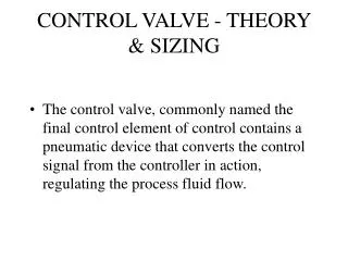
Control Valve. Instrument Training Material. Control Valve. Final Control Element Most widely used Other types of final control elements are Dampers or louvers Variable pitch fan blades. Final Control Element. Final Control Element. Considered as the muscle of automatic control.

E N D
Control Valve Instrument Training Material
Control Valve • Final Control Element • Most widely used • Other types of final control elements are • Dampers or louvers • Variable pitch fan blades
Final Control Element Final Control Element • Considered as the muscle of automatic control. • They furnish the necessary power application between the low energy levels of controllers and the high energy level needed to perform their function in control of the process.
Final Control Element Final Control Element
Control Valve • A power operated device that manipulates the fluid flow rate, temperature, level in a process control system. • It consists of a valve connected to an actuator mechanism that is capable of changing the position of a flow-controlling element within the valve in response to a signal from the controlling system.
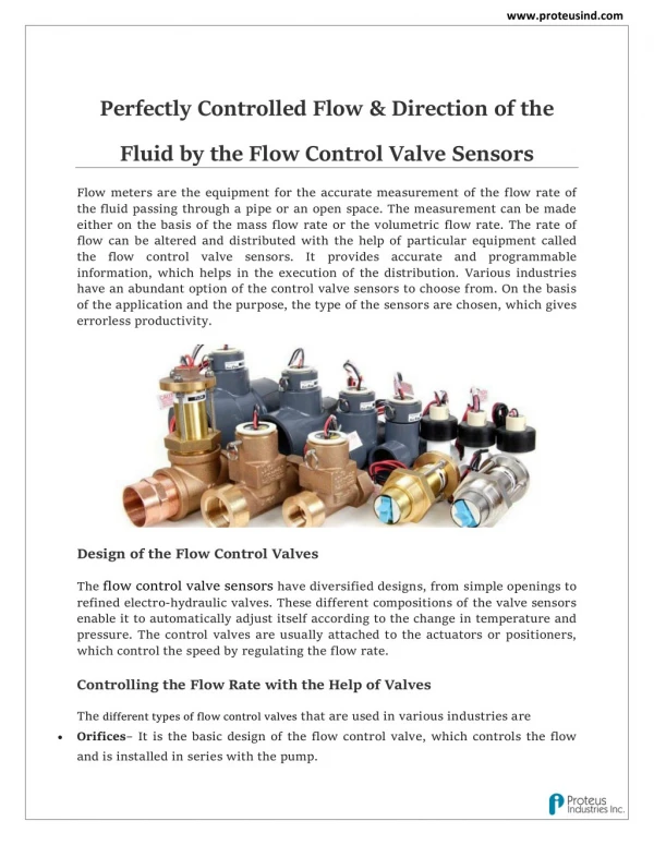
Control Valves • Functions as a variable resistance, creating a variable pressure drop in a pipeline • This pressure-drop process is often called throttling • It is consists of three major sub-assemblies: • The valve body assembly • The internal trim parts • An actuator assembly • Variety of additional valve accessories
Control Valve Actuator Assembly Valve Positioner Valve Body Assembly
Actuator • The power to drive the valve. • Power source could be: • Manual. • lever or gear box. • Pneumatic. • Hydraulic. • Electrical driven.
Valve Positioner • Control element determine the opening or closing position, action and characteristic of the valve. • It receive signal from controller. • It converts the signal to the appropriate opening or closing setting of the valve. • It provides the accurate control of the valve.
Valve Body • The part of a valve that is the main pressure boundary, • providing pipe connecting ends, • the fluid flow passage way, • in some cases, the part that supports the seating surfaces and closure member.
Control Valve Size varies from 1” to 36” valve body!
Control Valves Components - Although there are so many types and makes of control valves, this drawing can be used to illustrate the location and description of the different components of control valve. The main difference mainly will be the type of actuator used by different manufacturers.
Body Construction • In order to fulfill the control valve function, the valve body must: • Withstand the maximum operating pressure. • Have adequate capacity in respect of flow area. • Have correct flow characteristic. • Be able to resist erosion and corrosion.
Valve Body DN 100 . P13001 . 3 309 Line Size in metric units Pipeline Number Rating of the Piping Equipment Material Composition of Piping Equipment • All wetted parts of the control valve, including external bolts/studs and nuts must be designed to the same rating or equivalent piping class. • On the PEFS’s you will find the following information:
Piping Class • The piping classes are divided in different sections and the International Standard ANSI B.16.34 are applicable with the exception of the Classes 125, 250 and 400 • The following Classes are used and their abbreviations: • 1 = Class 150 • 3 = Class 300 • 6 = Class 600 • 9 = Class 900 • 15 = Class 1500 • 25 = Class 2500
Body Size • The control valve body size may have the same size as the calculated trim size, but oversized bodies, up to the size of the adjacent piping, may be required to reduce the outlet velocity of the fluid • The control valve body size shall be selected from the following series: • Metric Sizes: DN 25, 40, 50, 80, 100, 150, 200, 300, 400, 450, 500, 600, and larger • Imperial Sizes: 1”, 1-1/2”, 2”, 3”, 4”, 6”, 8”, 10”, 12”, 16”, 20”, and larger
Valve Trim Reduced trim means bore size smaller than port size Full trim means bore size = port size.
End Connections Integral Flange Separable Flange • The following are the possible connections for control valves. Normally, all control valves should have flanged ends. • Some types of control valves, such as Camflex Valves and Butterfly Valves do have flangeless valve bodies, which are less expensive.
End Connections Socket-weld Butt-weld Screwed Threaded connections are not permitted for process fluids. Allowed only for instrument air regulators if flange type cannot be obtained
Globe Valves • is the most widely used control valve in process control • provides tight shut off • withstand high differential pressure • changeable flow characteristic • by using different plug style offers a wide range of sizes, pressure ratings, and flow characteristics
Globe Valves • Single Seated Globe Valves: • This is the most preferred type for all applications with the exception of very high flow rates in combination with low pressure drops
Globe Valves • Double Seated Globe Valves - provides large capacities and ideal for high pressure applications with dirty fluids • Disadvantages • high leakage rate • very expensive
Globe Valves • Angle-Body Globe Valve - • This type of valve is designed specifically for erosive liquid and gas applications. Normally installed with the flow entering at the side and leaving at the bottom
Globe Valves • 3-Way Globe Valves: • For combining or diverting flow applications; provide large flow with low-pressure recoveries.
Flow Characteristics • Control valve Flow characteristics is the relationship between flow rate through the valve and valve travel as the travel is varied from 0 to 100% • CV: The VALVE FLOW COEFFICIENT is the number of U.S. gallons per minute of 60 degree F water that will flow through a valve at a specified opening with a pressure drop of 1 psi across the valve. • Inherent flow characteristic: refers to the characteristic observed with at constant pressure drop across the valve
Flow Characteristics • The three most common types of flow characteristics are: • Equal percentage - The inherent flow characteristic, which, for equal increments of rated travel, will ideally give equal percentage changes of the existing flow Cv at constant Delta P. • Linear - equal increments of travel provide equal increments of flow Cv at constant pressure drop.
Flow Characteristics • Cont…. • Quick opening – Provides for maximum change in flow rate at low valve travels with a nearly linear relationship. Additional increases in valve travel give sharply reduced changes in flow rate. Quick open plugs are used for on-off applications designed to produce maximum flow quickly.
Flow characteristics of globe valves can be deter-mined by the shape of the plug head.
Cavitation • A two-stage phenomenon of liquid flow • The first stage is the formation of cavities (vapor bubbles) within the liquid stream • The second stage is the collapse or implosion of those cavities (beyond the vena contracta) back into an all liquid state • The energy released by cavitating liquids can, under certain circumstances, cause physical damage of valve or piping components
Cavitation Pressure P1 Pressure P2 Velocity Liquid Vapor pressure PVc Pv Velocity
Anti-Cavitation Valves - For liquid services in which high pressure drops occur, the application of a conventional trim with standard flow direction often results in very high velocities and cavitation. This type of application requires anti-cavitation valve. Low Noise Valves - Liquid flow noise, cavitation noise, and flashing noise can be generated by the flow of a liquid through a valve and a piping system. Special design of control valve is necessary to reduced the noise level to acceptable value.
Flashing Pressure P1 Pressure PVc Velocity Liquid Vapor pressure Pv Velocity P2 • The liquid pressure drops below the vapor pressure and remains as vapor until the downstream pressure recovers. • Flashing will cause choke flow condition to occur. • In addition the vapor bubbles can also cause mechanical damage to the valve and piping system.
Cavitation & Flashing Recovery Point Cavitation point
PTFE Internal Lining Packing Box and Bellows Seal - The packing box or stuffing box is the most commonly used stem seal. The bellows seal is used only for highly toxic process fluid where leakage is not permissible. For services with fluid temperature outside the packing material temperature limits, an extended bonnet is used. Also for very low temperature service, an extended bonnet is selected to prevent ice formation on the stem. Extended Bonnet Standard Bonnet Packing box contains a number of compressed packing to maintain seal. Bellows seal is used for corrosive or highly toxic fluids.
VariPak Control Valve made by Masoneilan Advantages: Adjustable CvCan be adjusted from 100% to 40 % without any change of input signal and/or control valve components Large Cv range is achieved by changing different plugs and different shape of seat. Miniature Valves - are used for very small flows size DN 25 (1”) and smaller.
Eccentric Rotary Plug Valve (Camflex) Camflex Valve • Can be substituted for globe-body control valve. • The seat portion of the plug has the form of a spherical segment which is rotated through 50 degrees for maximum opening. • The design eliminates high torque and rapid wear of seat ring. • The tight shut off is achieved through the flexing action of the plug legs.
Rotary Globe Valve (Varimax) Varimax Valve • Provide control of high pressure compressible fluids without the erosion, vibration and high noise levels associated with conventionally designed rotary valves. Because of their relatively large flow passages they are particularly well suited for applications involving gases.
Butterfly Valve • High flow rate • Low pressure drop • Consists of a cylindrical body with a disk or vane. • Advantage - reduces the likelihood of clogging. • Disadvantages • Not tight shut-off • Flow characteristic cannot be change
Ball Valve • Similar to a butterfly valve except that its flow-control element is a sphere instead of a disk, and thus has a greater seating area. • Because of this, ball valves allow higher differential pressures and better sealing. • Normally used for on-off service (like emergency shutdown application). • The ball valve is not ideal for throttling service.
Actuators Diaphragm Spring Diaphragm Actuator Spring Set of Springs Fail Open Fail Close Multi-Spring, Spring Diaphragm Actuator Diaphragm Fail Open Fail Close Spring-Opposed Diaphragm Actuator
Spring-Opposed Piston Actuator • Long-Stroke Piston Actuator
Positioner Schematic for spring-diaphragm actuator or spring-opposed piston actuator.
Control Valve Accessories • Filter Regulators - For control valves which cannot handle the maximum air supply pressure of up to 8 Bar, they are provided with Air Filter Regulator. • Filters - For actuators which can handle the maximum air pressure, a Air Filters is used instead of Air Filter Regulator.
Control Valve Accessories • Handwheels - For control valves which needs to be open manually, in most cases during plant start-up, require hand wheel. The hand wheel facility is designed such that one man can operate the valve. • Limit Stops are provided to prevent the control valve from fully closing or fully opening.
Control Valve Accessories • Limit Switches are installed in control valves to electrically indicate open, closed, or intermediate position of the valve stroke • Limit switches can either be • micro-switches enclosed in an explosion proof box • or proximity sensors
Volume Boosters are used on throttling control valves to provide fast stroking action with large input signal changes. Depending on the actuator size, packing set and the number used, boosters can decrease valve stroking times by as much as 90%. Lock-up Valves are used for control calves which must stay-put (remains at last position) in case of an instrument air failure. They are known also as Stay-Put Valves. Quick-Exhaust Valves are applied to achieve a specified opening or closing time Solenoid Valves are used to interrupt or cut-off air signal to the actuator. It is used to switch a particular control valve or ESD shut-off valve to their fail safe position (Fail Close or Fail Open).
4 - 20 mA From DCS Schematic of Control Valve Basic Piping I Current to Pneumatic Transducer P Pneumatic Signal 3 - 15 PsiG Valve Actuator PneumaticPositioner Output To Actuator Regulated Air Supply Setting dependent on Actuator operating pressure Valve travel Feedback to Positioner Instrument Gauges
4 - 20 mA From DCS I Current to Pneumatic Transducer P Pneumatic Signal 3 - 15 PsiG Pneumatic Positioner Valve Actuator Output To Actuator Regulated Air Supply Setting dependent on Actuator operating pressure Valve travel Feedback to Positioner Instrument Gauges Schematic of Double Acting Control Valve Piping
Example of ControlValve Piping Schematic Drawing Set 3.4 Barg Lock up Valve Exh A B C Exh Trip Valve Set 2.8 Barg D E F Signal 4-20mA POSIT- IONER Air Regulator Set 3.8 Barg Check Valve Booster Relay Volume Tank Air supply The valve remains at last position incase of Air Failure.