Download
1 / 16
160 likes | 317 Views
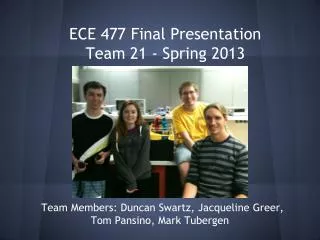
ECE 002 Final presentation. (from left to right) ASHLEY FRIEND, SUBHASIS GHOSH, EMMANUELLE DORVIL, DHRUV GAUR. GROUP WORK 2009. Equal contribution and enthusiasm makes our presentation a success.

E N D
ECE 002 Final presentation (from left to right) ASHLEY FRIEND, SUBHASIS GHOSH, EMMANUELLE DORVIL, DHRUV GAUR
GROUP WORK 2009 Equal contribution and enthusiasm makes our presentation a success. Dhruv and Subhasis in charge of presentation, Ashley and Emmanuella in charge of report writing. This presentation will demonstrate the work done in the ECE 002 class.
Sensor Characterization • Resources Purpose: To understand the way a variety of sensors can be used and to test values that will come from using these sensors • Top Hat Sensor • Analog sensors
ROBOT IN A MAZE Purpose: To create a robot that would successfully navigate a maze • Handyboard • Two Motors • Bumper Sensor, Sonar Sensor, and • Two Analog Light Sensors • Legos
void main() • { • inti=1; //defines the beginning of the count • while(start_button()==0); • while(i<4) //will repeat the while loop until the count is equal to four • { • motor(0,20); • motor(3,20); • if(digital(13)==1) //if the bumper sensor is hit • { • motor(0,-15); • motor(3,-15); • sleep(1.0); • ao(); • //sleep(1.5); • printf("\n%d",sonar()); • if(sonar()<360) //senses whether or not there is a wall on its side, if there is a wall there • { • motor(0,50); • motor(3,-20); • sleep(1.3); • i++; • } • else //if there is no wall next to the robot • { • motor(0,-20); • motor(3,50); • sleep(1.3); • i++; • } • } • while(analog(4)<200) //senses whether or not the robot is at the finish line • { • motor(0,20); • motor(3,20); • } • ao(); • } • } ROBOT...(contd..) Methods: We tested the sensors for their ranges Created the robot from legos Made corrections to structure or code as necessary Conclusion: Allowed us to understand the relationship between coding and sensors Challenges: Analog sensor troubles Keeping the robot in one piece Incorrect turns Misaligned gears
ELEVATOR • Resources Purpose: To create an elevator from legos that will go up and down • Handyboard • Analog sensors • Legos
ELEVATOR...(contd..) CODE: void main() { while(1) { if(start_button()==1) { If(analog(2)>200) { ao(); } else { motor(0,20); motor(3,20); sleep(2.0); motor(1,5); motor(3,5); } } if(stop_button()==1) { if(analog(3)>200) { ao(); } else { motor(0,-20); motor(3,-20); sleep(2.0); motor(0,-5); motor(3,-5); } } } }
INSTRUMENTATION • Resources OBJECTIVE • Understanding Oscilloscopes • Applying it to the study of waves • Applying to understand AC and DC signals PROCEDURE • Set the channel and trigger mode • Attach the BNC cable and the mini • Adjust the time dial and then set up the position dial so as to center the green line on the screen • Set the DC voltage using the VOLTS/DIV dial • Finally connect the mini grabber strips to the power supply • Oscilloscope DC Power Supply
RESULTS 5 volts/division 5 microseconds time/div A = [1 2 0; 2 5 -1; 4 10 -1]; B = [20; 35; 45] X = inv(A) * B X = 80 -30 -25 Time = 5 microseconds Voltage = .2 volts/div
CIRCUITS • Resources PURPOSE • Construct variety of circuits • Understand the application of Ohm’s Law, breadboard, multi-meter • Measure voltage change across the resistors upon using different values of resistance METHOD • Connect the resistors onto the breadboard in either series or parallel • Attach the mini grabber plugs in order to measure the voltage across • Use the 1k ohm resistor in series and parallel and measure the voltage across it using the multi-meter • Replace the 1k ohm resistor by a 2 k ohm resistor and measure the voltage across it • Breadboard • Resistors- 1k, 2k ohm • Diode • Mini-grabber cables • DC power supply • Multi-meter
RESULTS The results helped to confirm the group’s knowledge of Ohm’s Law and circuits. The lab was fairly straight forward but the equipment was confusing Connecting the multi-meter to the circuit voltage was confusing With practice we learned exactly where the multi-meter needed to achieve the desired voltage. This was an important project as major portion will be discussed further in the ECE program as well as for future jobs in electrical areas.
PSPICE PURPOSE • To use the PSPICE program on the computer and simulate circuits • Calculate voltage and current across the circuit at different points Method • Place the resistor, voltage source, grounding source on the page • Complete the circuit by connecting all the elements with a connecting wire • Check for a red dot on the connecting spots • Current and voltage probes were placed on the necessary place to measure voltage/current • Run the program in order to produce the graph with results of the circuit • Add 3 resistors 100 ohm, 300 ohm, and 200 ohm in series and a voltage source 6 V • Find the current through the circuit • Replace the circuit by 2 resistors 200 ohm and300 ohm in parallel such that the current through them is 60 mA and 80 mA respectively • Find the voltage across each resistor and entire circuit • Replace the circuit by a diode whose threshold voltage by 0.7 V, a resistor of 1k ohm, and a source voltage of 1.7 V and then 0.3 V • Find the current across the diode and resistor, and voltage drop across the diode • Replace the circuit by a diode of threshold voltage 0.7 V, two resistors 1k ohm in parallel, and a resistor 1k ohm in series with the parallel resistors • Find the current through the circuit • PSPICE (Simulation program with Integrated circuit emphasis) computer program
RESULTS This program was fairly simple to use since the group had already done circuits Problems that arose were how to use the program and where to place the probes. PowerPoints were helpful in understanding Helped the group understand more complicated circuits
MATLAB MATLAB was used to solve for functions Varx = input('What is the first number?');Vary = input('What is the second number?');Varz = input('What is the third number?'); Vargroup5= group5(Varx, Vary, Varz) % num2str converts a number to a string. function w=group5(x,y,z) w=(x+y+z)/3; function I=trapz(f,a,b,n)h =(b-a)/n;s = feval(f,a); for i=1:n-1 x(i)=a+i*h; s=s+2 * feval(f,x(i));ends=s+feval(f,b);I=s*h/2; fon=inline('log'); a=exp(1); % Starting point.b=2*a; % Ending point.n=10000; % Number of intervals. tic % Start counter.OutValue1=trapz(fon, a, b, n) % Calling Trapezoidal function.toc tic % Start counter.OutValue2=FastTrap(fon, a, b, n) % Calling Trapezoidal function. Toc fon=inline('log'); a=exp(1); % Starting point.b=2*a; % Ending point.n=10000; % Number of intervals. tic % Start counter.OutValue1=trapz(fon, a, b, n) % Calling Trapezoidal function.toc tic % Start counter.OutValue2=FastTrap(fon, a, b, n) % Calling Trapezoidal function. Toc function I=FastTrap(f, a, b, n) % Same as the previous Trapezoidal function example, but using more% efficient MATLAB vectorized operations. h=(b-a)/n; % Increment values=feval(f, a); % Starting value in=1:n-1; xpoints=a+in*h; % Defining the x-pointsypoints=feval(vectorize(f),xpoints); % Get corresponding y-pointssig=2*sum(ypoints); % Summing up values in ypoints, and mult. by 2s=s+sig+feval(f,b); % Evaluating last termI=s*h/2; function I=trapz(f,a,b,n)h =(b-a)/n;s = feval(f,a); for i=1:n-1 x(i)=a+i*h; s=s+2 * feval(f,x(i));ends=s+feval(f,b);I=s*h/2;