Download
1 / 28
280 likes | 450 Views
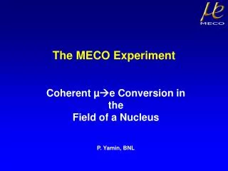
The MECO Experiment at BNL. William Molzon University of California, Irvine April 22, 2004 Review of Brookha v en National Laboratory Particle Physics Program. Goal of This Talk. Remind reviewers of the physics motivation and the status of related experiments that bear on the same physics

E N D
The MECO Experiment at BNL William Molzon University of California, Irvine April 22, 2004 Review of Brookhaven National Laboratory Particle Physics Program
Goal of This Talk • Remind reviewers of the physics motivation and the status of related experiments that bear on the same physics • Remind reviewers of the experimental techniques and critical requirements • Go through the systems, indicating status of each and the needs of the collaboration • Point out the areas in which BNL Physics Department, C-AD, and other Departments’ personnel are making contributions W. Molzon The MECO Experiment at BNL
Osaka University M. Aoki, Y. Kuno, A. Sato Syracuse University R. Holmes, P. Souder College of William and Mary M. Eckhause, J. Kane, R. Welsh Boston University J. Miller, B. L. Roberts Brookhaven National Laboratory K. Brown, M. Brennan, G. Greene, L. Jia, W. Marciano, W. Morse, P. Pile, Y. Semertzidis, P. Yamin University of California, Irvine C. Chen, M. Hebert, W. Molzon, J. Popp, V. Tumakov University of Houston Y. Cui, E. V. Hungerford, N. Klantarians, K. A. Lan University of Massachusetts, Amherst K. Kumar Institute for Nuclear Research, Moscow V. M. Lobashev, V. Matushka New York University R. M. Djilkibaev, A. Mincer, P. Nemethy, J. Sculli, A.N. Toropin MECO Collaboration Active BNL Personnel (UCI funding / BNL funding) Wuzheng Meng – Liaison Physicist Dave Phillips – Liaison Engineer Jon Hock – mech. engineer Bill Leonhardt (Ph) – mech. engineer Mike Iarocci* – cryo engineer Dan Weiss – vacuum engineer Peter Wanderer (SMD) – magnet engineer Active MIT Personnel Brad Smith – Magnet Subsystem Manager Alexi Radovinsky – engineer Peter Titus – mechanical engineer W. Molzon The MECO Experiment at BNL
e W What Will Observation of -N e-NTeach Us? • Discovery of -N e-Nor a similar charged lepton flavor violating (LFV) process will be unambiguous evidence for physics beyond the Standard Model. • For non-degenerate neutrino masses, n oscillations can occur. Discovery of neutrino oscillations required changing the Standard Model to include massive . • Charged LFV processes occur through intermediate states with n mixing. Small n mass differences and mixing angles expected rate is well below what is experimentally accessible. • Charged LFV processes occurin nearly all scenariosfor physics beyond the SM, in many scenarios at a level that MECO or PSIMEG will detect. • Effective mass reach of sensitivesearches is enormous, well beyondthat accessible with direct searches. One example of new physics, with leptoquarks lmd led W. Molzon The MECO Experiment at BNL
10 -11 10 -10 10 -13 10 -12 10 -15 10 -14 10 -17 10 -16 10 -19 10 -18 10 -20 10 -21 Supersymmetry Predictions for LFV Processes • From Hall and Barbieri Large t quark Yukawa couplingsimply observable levels of LFV insupersymmetric grand unified models • Extent of lepton flavor violation in grand unified supersymmetry related to quark mixing • Original ideas extended by Hisano, et al. Current MEGA bound Current SINDRUM2 bound B( e g) Re PSI-MEG single event sensitivity MECO single event sensitivity 100 200 300 100 200 300 W. Molzon The MECO Experiment at BNL
Expected Signal and Background in MECO Experiment Background calculated for 107 s running time at intensity giving 5 signal event for Rme = 10-16. Sources of background will be determined directly from data. 5 signal events with0.5 background events in 107 s running if Rme = 10-16 Recent understanding of AGS operating schedule and conditions reduces proton flux and running time per year. W. Molzon The MECO Experiment at BNL
Potential Sources of Background Muon decay in vacuum: Ee < mc2/2 Muon decay in bound orbit: Ee < mc2 - ENR - EB • Muon Decay in Orbit – • Emax = Econversion when neutrinos have zero energy • dN/dEe (Emax – Ee)5 • Sets the scale for energy resolution required: ~200 keV • Radiative Muon Capture: - N N(Z-1) • For Al, Egmax = 102.5 MeV/c2, P(Eg > 100.5 MeV/c2) = 4 10-9 • P(g e+e-, Ee> 100.5 MeV/c2) = 2.5 10-5 • Restricts choice of stopping targets:Mz-1 > Mz • Radiative Pion Capture: • Branching fraction ~ 1.2% for Eg > 105 MeV/c2 • P(g e+e-, 103.5 < Ee< 100.5 MeV/c2) = 3.5 10-5 • Limits allowed pion contamination in beam during detection time, sets requirement for a pulsed beam W. Molzon The MECO Experiment at BNL
Features of MECO • 1000–fold increase in m beam intensity over existing facilities • High Z target for improved pion production • Axially-graded 5 T solenoidal field to maximize pion capture Superconducting Solenoids Muon Beam 1 T 1 T Calorimeter 2 T Straw Tracker Stopping Target Foils Proton Beam 2.5 T • Pulsed beam to reduce one class of backgrounds • Muon stopping region and detectors designed for high acceptance and high rate capability 5 T Pion Production Target W. Molzon The MECO Experiment at BNL
How Have We Allocated Resources? • Try to keep critical path items on schedule. • Magnet system was (and still is) critical path item. Current estimate is 42 months from signing engineering design contract to operating system. Try to keep design moving even without MREFC start. This has been an NSF priority in their request to Congress • Try to retire technical and cost risk as early as possible. • Fund items that will allow technology choices to be made, prove systems that are technically risky, etc. • Examples are tracking system and calorimeter system • Give priority to funding design work that will allow construction funds to be used efficiently when available – this has been a moving target. • Give priority to keeping collaboration intact by providing funding for items on which collaborating institutions are actively working, using their base funding grants. • Give reduced priority to funding items that are not on the critical path and for which the outcome is not in doubt and there is a clear path to doing the necessary engineering. • Allocation scheme has certain problems. • We risk missing some critical items if unforeseen problems arise after thinking and design work starts. • With inadequate resources, more items develop inadequate schedule contingency as no work is done on them – everything eventually becomes critical path. • As people are brought on board, increasing fraction of available resources goes to keeping them paid, leaving no resources for them to do anything. W. Molzon The MECO Experiment at BNL
Intense, Pulsed Proton Beam from AGS for MECO (WBS 1.1) • MECO goal: 8 GeV beam, 41013 protons per second. • Current problem – intensity limited to 21013 due to activation limits in booster. Sensitivity loss of factor of 2 if unsolved. • Cycle time of 1.0 s with 50% duty factor • Revolution time = 2.7 ms with 2 of 6 RF buckets in which protons are trapped and accelerated • 1.35 msec pulse spacing • Resonant extraction of bunched beam • Very good extinction needed • <10-9 protons between bunches for each proton in bunch • Stopped muon lifetime matched to pulse spacing: • aluminum or titanium Proton pulse Proton pulse Detection time Promptbackgrounds Michael Brennan of C-AD is AGS Modifications Subsystem Manager – currently no funding exists for design of AGS modifications, tests to reduce losses and understand beam. W. Molzon The MECO Experiment at BNL
Removing Out-of-Bucket Protons in the AGS Extinction measurements: • Initial test at 24 GeV with one RF bucket filled yielded <10-6 extinction between bucketsand 10-3 in unfilled buckets • A second test at 7.4 GeV with a single filled bucket found <10-7 extinction • Improvements in extinction in the AGS: • 40 kHz AC dipole used to destabilize all orbits • Fast kicker magnets to cancel effect of AC magnet for particles in buckets (field shown inverted). • Some early tests done • Changes needed • Modifications to kicker for continuous operation • Controls modifications magnetic kick Additional, extensive facility renovation and improvements for increased reliability during extended, high current running currently under study W. Molzon The MECO Experiment at BNL
Proton Beamline (WBS 1.2) • K. Brown (BNL) is Proton Beamline Subsystem Manager • Proton beamline is designed for achromatic transport of 8 GeV protons to muon production target (Phil Pile and Kevin Brown) • Includes RF modulated magnet plus Lambertson septum magnets to separate filled buckets from other particles in beam • Pre-conceptual design of RFMM done at UCI • Stripline magnet with ferrite return yoke • Provides ~2.1 mrad separation between filled/unfilled buckets ( uniform 75 Gauss field, 5 m long) • Resonantly driven at 771 kHz, Q of ~100, for efficient operation • Plan to do conceptual design study of total system -2.500 0.000 2.500 I**---**---**---**---**---**---*I 0.8 I 11 I 0.6 I 13DJTSXED I 0.4 I 8$$$$$$$$X I 0.2 I $$$$$$$$$$1 I 0.0 I 1$$$$$$$$$$6 I -0.2 I $$$$$$$$$$4 I -0.4 I $$$$$$$$$$ I -0.6 I L$$$$$$$$F1 I -0.8 I 27HNKODB6 I -1.0 I 11 1 I -1.2 I I -1.4 I 21574761 I -1.6 I 7W$$$$$$V8 I -1.8 I $$$$$$$$$$ I -2.0 I 2$$$$$$$$$$4 I -2.2 I $$$$$$$$$$5 I -2.4 I 3$$$$$$$$$$3 I -2.6 I O$$$$$$$$$ I -2.8 I 1L$$$$$$K2 I -3.0 I 1123 2 2 I -1.4 I I I**---**---**---**---**---**--**I Unfilled bucket Unfilled bucket Filled bucket Filled bucket W. Molzon The MECO Experiment at BNL
Additional Proton Beamline Work • Shielding design in progress (Dave Phillips) • Potential extraction aperture limitations recently found (K. Brown) • Instrumentation design in progress (Kevin Brown) • Possible complete redesign/simplification of switchyard being considered – potential for up-front spending to reduce significantly operating cost and increase operating reliability (Phil Pile) • Significant facility refurbishment/modification under study • Considered necessary for extensive high intensity running W. Molzon The MECO Experiment at BNL
Production Target and Heat Shield (WBS 1.3) Production target region designed for high yield of low energy muons: • High Z target material • Little extraneous material in bore to absorb p/m • Diameter 0.6 - 0.8 mm,length 160 mm • ~5 kW of deposited energy • Water cooling in 0.3 mm shellsurrounding target • Simulated with 2D and 3D thermaland turbulent fluid flow finite element analysis • Target temperature well below 100 C • Pressure drop is acceptable ( ~10 Atm) • Prototype built, tested for pressureand flow Fully developed turbulent flow in 300 mm water channel inlet detail target rod Inlet detail W. Molzon The MECO Experiment at BNL
Target Heat Shield • Protects solenoids from radiation load • Optimized to reduce total load on magnet cold mass to ~100 W (UCI) • Approximately 10 kW of power deposited • Combination of copper and heavymet • Supported off PS cryostat inner wall • Work on construction technique and water cooling mechanism • Structural and thermal analysis by Jon Hock (BNL -- UCI contract) • Study of activation levels by Peter Yamin (BNL) Installation gantry concept by Jon Hock Thermal analysis by Jon Hock (BNL) W. Molzon The MECO Experiment at BNL
Superconducting Magnet System (WBS 1.4) Short history of development • Group at National High Magnetic Field Laboratory at FSU did a pre-conceptual design study of magnet system. • Group at MIT Plasma Science and Fusion Center was chosen by competitive bid to do a conceptual design study, following advice of a Magnet Review Committee appointed by MECO. • A conceptual design report was issued. The work was internally reviewed twice (interim and final review) by a panel of experts appointed by MECO. • A Magnet Acquisition Panel convened jointly by BNL and MECO endorsed an acquisition plan involving a commercial, build-to-specification procurement. • Three industrialization studies were completed with private industrial concerns. • Insulation system for the coils and joints – recommended epoxy and other material choices for radiation hard fabrication • Winding, impregnation logistics, fabrication cost and schedule – concluded that the magnets can be built commercially within the nominal 41 month schedule for a price consistent with our expectations • Refrigerator/liquefier— refurbish or buy new recommendation • At MECO’s request, multiple Laboratory safety committees reviewed the conceptual design. • An agreement was reached with an experienced procurement group at LLNL to work with UCI to procuring the magnet system, with UCI to write the contract. • A detailed Magnet Acquisition Plan has been drafted (MIT/UCI/LLNL). • A Statement of Work and Technical Specification for the magnet engineering design, construction and installation have been drafted and reviewed by many people at BNL including SMD, C-AD, and safety committees. Recommendations of these various groups have been incorporated into the documents. • An RFP for the procurement has been drafted. • A first meeting with potential vendors was held at MT18 Conference in October in Morioka. W. Molzon The MECO Experiment at BNL
MIT Plasma Science and Fusion Center Conceptual Design of MECO Magnet System 5 T 2.5 T • Very detailed CDR completed (300+ pages) • Complete 3D drawing package prepared • TS and SOW for commercial procurement developed • Industrial studies contracts let and completed 2 T 1 T 1 T • 150 MJ stored energy • 5T maximum field • Uses surplus SSC cable • Can be built in industry W. Molzon The MECO Experiment at BNL
Recent Technical Magnet Progress • The structural models of PS, TS and DS magnets have been updated from the CDR to incorporate some changes and to evaluate effects of modulus and coefficient of thermal contraction variations and deadweight effects. • New PS iron return yoke and partial pole piece incorporated to reduce fringe fields and provide ground water shielding • PS coil lengths and builds revised to improve manufacturability • DS partial iron pole piece incorporated to reduce fringe fields • TS cryostat pedestals widened to better react bending stresses • Downstream TS horizontal support modified to accommodate DS pole • Studies done to understand required manufacturing tolerances (MIT/UCI) • Cumulative and non-cumulativemachining tolerances and assembly tolerances • Coil winding tolerances • Materials tolerances • Alignment tolerances • Preliminary conclusion is thatall tolerances are well within typical capabilities of vendors • Redesign of 80 K thermal shieldsto allow He gas cooling • Planned cable tests • Short sample conductor tests • Test of soldering cable in conduit • Extracted strand tests of cable • Work to define installation interfaces (Dave Phillips) PS strain TS model DS strain W. Molzon The MECO Experiment at BNL
Magnet Acquisition Plan • Assumes the final design, fabrication, installation and acceptance testing will be performed by a commercial vendor or a team of vendors. • Identifies method as Best Value Source Selection • Identifies firms with required capabilities or known to have an interest: • Alahlam Ltd. • Ansaldo Superc • ACCEL • Babcock Noell Nuclear GmbH • Cryogenic Ltd. • General Atomics • Hitachi • Establishes a fixed price, contract as the preferred option – allows for industry feedback at draft RFP stage • Discusses possibility of splitting out high cost risk interface items and/or installation • Establishes management information requirements – reporting, QA, etc. • Mitsubishi Electric Corp. • Oxford Instruments • Sigmaphi • Space Cryomagnetics • Toshiba • Wang NMR Inc. W. Molzon The MECO Experiment at BNL
Muon Beamline (WBS 1.5) • Primarily for magnet interface purposes – not a critical path item • W. Morse (BNL) is subsystem manager • Work on vacuum window at midpoint of transport solenoid by Dan Weiss (UCI contract) • Interaction with MIT/UCI on specification • Separates dirty PS vacuum from clean DS vacuum • Serves as antiproton absorber • Conceptual design complete • Work on vacuum system and TS end flange closure • Vacuum spec and pump selection by J. Popp (UCI) and Dan Weiss (BNL / UCI contract) • Mechanical design/layout by P. Nemethy (NYU) and Bill Leonhardt (BNL Physics BNL/UCI support) • Studies of radiation levels in DS region and effect of boron and lithium loaded polyethylene by Peter Yamin. W. Molzon The MECO Experiment at BNL
Tracking Detector (WBS 1.6) • Two tracker geometry options are being considered • Longitudinal geometry with ~3000 3m long straws oriented nearly coaxial with the DS and 19000 capacitively coupled cathode strips for axial coordinate measurement • Transverse geometry with ~13000 1.4 m straws, oriented transverse to the axis of the DS, readout at one or both ends • Both geometries appear to meet physics requirements Longitudinal Tracker W. Molzon The MECO Experiment at BNL
Cathode Pad Resolution Spiral straw s(mm) Seamless straw Angle (deg.) Seamless Straw Development (Osaka) • Seamless straws • Thickness : 25 mm • Diameter : 5 mm • Material : Polyamide + Carbon • Resistance : 6 MW/sq • Advantages • No Adhesive • Thinner • More uniform thickness and resistance • Less out-gassing and leakage in vacuum • System built and tested in Japan • Cathode pad resolution • Seamless Straw (4MW/sq) Resolution s = 0.4 mm at 60° • Spiral Straw (0.5MW/sq) Resolution s =1.1 mm at 60° • Design goal (s = 1.5 mm) is achieved • Seamless straw anode performance • Drift Distance Resolution s = 70 mm at 60° • Efficiency > 95% except near walls • Design goal (s = 0.2 mm) is achieved W. Molzon The MECO Experiment at BNL
Tracker R&D (Houston) • Studies provide input to select geometry and readout architecture • Full-length longitudinal vane prototype remains a work in progress at Houston as mechanical stability and straw bonding issues are resolved • Electronics design and prototype work at Houston has progressed to testing prototype preamplifier, digitizer, and controller boards as a system using the current version of BaBar’s Elefant chip with very promising results. • Work beginning on updating Elefant chip design to current technology • Simulations of both the longitudinal and transverse geometries continue, indications are that either geometry might work from a physics standpoint W. Molzon The MECO Experiment at BNL
Calorimetric Electron Detector - NYU (WBS 1.7) • Bench tests of PbWO4 crystals cooled to –23 °C and large area avalanche photodiodes continue at NYU using electronics designed and built in house • Indications are that this material will meet MECO resolution requirements, demonstrating 20-30 photo e-/MeV (as compared with CMS’ 5 pe/MeV) • We need to verify the system performance via beam tests of an 88 crystal array • If true we can sharply reduce the contingency on the Calorimeter that covered the possibility of using BGO crystals • Further it appears that we can make use of fewer (larger) crystals allowing reductions in APD, and associated HV and readout channel counts (1152 crystals vs. 2000 originally) Estimated W. Molzon The MECO Experiment at BNL
Cosmic Ray Shield (WBS 1.8) • Extensive testing at William & Mary has established a combination of scintillator, wavelength shifter, and multi-anode PMT that will meet MECO’s 99.9% cosmic ray veto efficiency requirement • Extrusion of ~100 4m slats this summer at Itasca – similar to MINOS design • Test slats will be assembled into a prototype module this Fall • Further concerns with rates (e.g. from neutrons) to be addressed Trigger and DAQ (WBS 1.9) • No engineering has gone into the Trigger or DAQ to date due to lack of resources. • A fraction of the support for Boston University’s Electronics Design Facility (EDF) will be devoted to start design for the system and cost it. W. Molzon The MECO Experiment at BNL
Management Structure (WBS 1.11) • Current Status • Full time Project Manager on board • No other project office personnel • Critical needs in MECO management structure: • Chief Mechanical Engineer – Candidates are being considered now; the person will lead integration effort and contribute to critical design needs in short term. • Chief Electrical Engineer – Attempting to identify candidates for the same type of integration and critical design jobs. • Cost and Schedule Manager – aid the PM in developing cost and schedule documentation. The person will work with integrated cost and schedule software (e.g. Primavera). W. Molzon The MECO Experiment at BNL
Summary • There has been substantial progress in systems where we have been able to apply resources. • A number of systems are (or soon will be) at the stage where construction funds can be efficiently spent. • Lack of pre-project development and R&D funds have been the limiting factor in developing the designs of most systems. • Lack of engineering and project manpower means less reliable cost estimates and resulting higher contingency required in the current cost estimate. • Many systems are close to being baselined, some with technology choices still to be made. • The critical path subsystem (the solenoids) have benefited from internal funding priority; nonetheless, they are being delayed (currently day for day) by a combination of less that adequate funding and procedural difficulties. • Some unforeseen problems with intensity limitations and with available running hours per year threaten to stretch the required years of running and decrease the ultimate MECO sensitivity. W. Molzon The MECO Experiment at BNL
What Can This Committee Do? • Encourage the Laboratory to support the experiment as much as possible. • Structure responsibilities of senior physicists such that they can devote intellectual effort to the experiment. • Encourage the DOE and Lab to appreciate the potential benefits of a successful experiment as well as the risks of possible failure. • Encourage the DOE (both NP and HEP) to provide appropriate support to the collaborating institutions. • Physicists in Physics Department • Physicists in C-AD and SMD • University groups supported by both NP and HEP • Encourage the Laboratory and the DOE to recognize that there is more than one way of doing business and to be flexible in interactions with the experiment (e.g. costing of limited periods of running with RHIC). • Encourage the Laboratory and the DOE to find a way to make adequate running time available (presumably at NSF cost). W. Molzon The MECO Experiment at BNL