Download
1 / 36
360 likes | 447 Views
ICFA Mini-Workshop on Novel Concepts for Linear Accelerators and Colliders. Laser-Driven Dielectric Structures and Linacs (Working group 2) E. R. Colby SLAC National Accelerator Laboratory July 8 th , 2009. Outline. Overview of technology

E N D
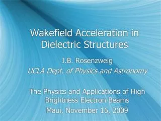
ICFA Mini-Workshop on Novel Concepts for Linear Accelerators and Colliders Laser-Driven Dielectric Structures and Linacs (Working group 2) E. R. Colby SLAC National Accelerator Laboratory July 8th, 2009
Outline • Overview of technology • Critical issues and requirements on other subsystems • First cut at a parameter list for a 1 TeV x 2e34 collider
P/l 2 Fluence [J/cm2] Peak Field [GV/m] 30cm 3cm 3mm 300m 30m 3m300nm Source Wavelength Pulse Length [ps] The Possibility of High Gradient B. C. Stuart, et al, “Laser-Induced Damage in Dielectrics with Nanosecond to Subpicosecond Pulses,” Phys. Rev. Lett., 74, p.2248ff (1995).
Question #1: How can lasers be used to efficiently accelerate particle beams?
“Lin” PBG Fiber er=2.13 (Silica) DIA=1.4l Zc=19.5W bg=0.58 1.305l X. (Eddie) Lin, “Photonic Band Gap Fiber Accelerator”, Phys. Rev. ST-AB, 4, 051301, (2001). • Can be designed to support a single, confined, synchronous mode • All other modes at all other frequencies radiate strongly
Planar Photonic Accelerator Structures Synchronous (b=1) Accelerating Field • Accelerating mode in planar photonic bandgap structure has been located and optimized • Developed method of optical focusing for particle guiding over ~1m; examined longer-range beam dynamics • Simulated several coupling techniques • Numerical Tolerance Studies: Non-resonant nature of structure relaxes tolerances of critical dimensions (CDs) to ~λ/100 or larger Y (mm) S. Y. Lin et. al., Nature 394, 251 (1998) This “woodpile” structure is made by stacking gratings etched in silicon wafers, then etching away the substrate. X (mm) Vacuum defect beam path is into the page silicon
Simple Variant: Fast Deflector T. Plettner et al, Phys. Rev. ST Accel. Beams 4, 051301 (2006) T. Plettner, submitted to Phys. Rev. ST Accel. Beams The Transmission Grating Accelerator Silica, l=800nm, Ez=830 MV/m
UCLA is designing, fabricating and testing a slab-symmetric, laser-driven, dielectric micro accelerator Periodic modulation in z is necessary to have an accelerating mode: a standing wave with kz = ω/βc. resonant structure with good Ez fields Device schematic; structure variation in x not shown Typical values (λ=1μm) a ~ 0.1 μm b ~ 0.3 μm number of periods ~ 1000 overall length ~ 1 mm z one period Gil Travish, UCLA
Optical Accelerator Structures under Study • Bragg Planar Dielectric Structure • Accelerating mode guided by two-sided Bragg multi-layer waveguide • Grating couples laser from side and converts it to accel mode • Have TiO2-SiO2 multi-layer wafers fabricated by ZC&R Coatings Inc; etching of gratings and spacer fab are next steps S. Tantawi & J. Guo, SLAC
Essence of the PASER L. Schächter, Phys. Rev. E 53, p. 6427, 1996 Levi Schächter, The Technion
Outline • Overview of technology • Critical issues and requirements on other subsystems • First cut at a parameter list for a 1 TeV x 2e34 collider
Critical Issue #1a: Efficiency! #1b: Gradient!
Efficiency optimization: Single-Pass and Recirculating A Lin-type Photonic crystal fiber is taken for the example here.
Gradient: Damage Threshold Measurements Proc. SPIE 6720, 67201M-1 Pump-Probe Apparatus developed for measuring the damage threshold of materials in the 1-3 micron range. Silicon promising, but gradients > 1 GeV/m in NIR unlikely B. Cowan, Tech-X
Impedance and Gradient Optimization Eaccel/Epeak d/a w/a Assuming 1ps laser pulse Ben Cowan, Tech-X d/a
Question #2: What is the best wavelength? • Question #2 (in more useful form): What is the best wavelength given: The geometric limitations of present and future fabrication techniques, Expectations for highly efficient power production in (e.g.) within 10-years, The breakdown behavior of suitable materials?
Progress in Laser Technology • Efficient pump diodes for CW operation • DARPA SHEDs program (80% wall-plug-to-light, CW) • JDS Uniphase has demonstrated >76% efficiency CW from room-temperature diode bars • Efficient materials • Yb:KGdWO4 disk lasers (marketed and R&D) • High-dopant concentration ceramic lasers (R&D) • Yb-fiber (1.1 m) • Th-fiber (1.75-2.1 m) • Ho-fiber (2.1, 2.8 m) • DOE SBIR program • Carrier Phase Locking (NIST) • Self-referencing demonstrated in 1999 • 5 fiber lasers optically phase-locked • PCF use in commercial high-average power applications
UCLA Phase Matching Projected power, 50 ps, L=2.5 cm n3n1 n2 Experiment 2004 MW, 250 ps pulses L=2.5 cm 10.6mm 340mm THz Power Density, kW/cm2 3x3x2.5 cm3GaAs Noncollinear Frequency Generation in a nonlinear GaAs Crystal using 2 CO2 laser lines 10.3mm Theory GaAs L=1 cm [111] THz beam CO2 laser beams Experiments 2002- 2007 kW 200 ns pulses 2 MW at 340 mm 0.5 mJ in a 250 ps pulse 2 kW tunable 0.5-2 THz pulse(0.4 mJ - 200 ns). Pump Intensity, MW/cm2 1. MW power THz pulses using Difference Frequency Generation (DFG) of CO2 laser lines in GaAs in a single-shot experiment. JAP, 98, 026101, 2005 2. kW power THz pulses using DFG of CO2 laser pulses in GaAs at a 1 Hz pulse repetition frequency. JOSA B, 24, 2509-2516, 2007 Narrow-Band, High-Power THz DFG Source Sergei Tochitsky, UCLA
Question #3: How can beam be transported through such a small aperture?
mm-mr Emittance and Beam Transport f If a is the beam hole radius, the acceptance is L For a quad of length l and gradient G Example R. Siemann, ARDB
Beam Transport • FODO lattice solution • Modest quad strengths (400-650 T/m, NB: aperture is <1 mm!) • Permanent magnet focusing elements are adequate • 500 T/m quad triplet already designed and in fabrication • Laser-driven focusing elements also considered • Tremendous strength possible: 800,000 T/m ! • Dynamic aperture studies completed for woodpile lattice First-Generation PMQ Triplet NdFeB/Iron Pole tips G=250 T/m Second-Generation PMQ Triplet NdFeB Halbach Design G=500 T/m Long-transport channel studies of beam propagation stability in laser-driven focusing lattices B. Cowan, PRST-AB, 11, 011301 (2008).
Question #4: How can efficient coupling between the power source and structure be achieved?
Input Waveguide Input Waveguide S11 = 0.66 Electric field “Shoulder coupler” for TE mode Example: Compact Fiber Couplers Single-mode fiber coupler for TM mode (metal WG) Single-mode fiber coupler for TM mode (dielectric WG) C. Ng, SLAC J. England, SLAC
Question #5: Can electron and positron sources can be made to provide suitable beams?
We are taking a three-pronged approach and deferring some issues typically of concern in HEP accelerators ➊ Metallic Cold Test ➋ Integrated “gun” ➌ All-dielectric structure Gil Travish, UCLA
Penning-Trap Optical injector: basic concept • Trapped electrons • Active medium • Electrons become bunched ,they extract energy from the medium therefore, the decay-rate of energy stored in the medium in enhanced. • Electrons that become bunched, escape the trap – optical injector Schächter; PRL, 102, 034801 (2009). Levi Schächter, The Technion
First-Pass Luminosity Calculation • Optical bunching within the short macropulses must be destroyed, otherwise beamstrahlung is unacceptably high. Can do this after acceleration with small R56. R. Siemann, ARDB
Outline • Overview of technology • Critical issues and requirements on other subsystems • First cut at a parameter list for a 1 TeV x 2e34 collider
Sample Parameters for a 1 TeV x 2e34 Collider Structure Candidates for High-Gradient Accelerators Maximum gradients based on measured material damage threshold data Photonic Crystal Fiber Silica, l=1890 nm, Ez=400 MV/m Photonic Crystal “Woodpile” Silicon, l=2200nm, Ez=400 MV/m Transmission Grating Structure Silica, l=800nm, Ez=830 MV/m Luminosity from a laser-driven linear collider must come from high bunch repetition rate and smaller spot sizes, which naturally follow from the small emittances required • Beam pulse format is (for example) • (136 microbunches of 1.8x10⁴ e- in 1 psec) x 25MHz • Storage-ring like beam format reduced event pileup • High beam rep rate=> high bandwidth position stabilization is possible
Average Power Handling Capacity of Fibers http://www.ipgphotonics.com/documents/documents/HP_Broshure.pdf
Some Questions – 1/3 • Power Source • What is the maximum efficiency of mode-locked, phase-locked fiber, crystal, and ceramic lasers? • How can sections ~100 meters apart maintain ~1o~50 attosecond temporal alignment? • Particle (Injector) Source • Can a compact, economical source of electrons be made? • How can positrons with the required qualities be produced?
Some Questions – 2/3 • Structure • What is the damage threshold for structure materials? • What are the nonlinearity-imposed field limits? • What are the thermal limitations for these structures? • What is the best way to couple power from lasers into the structures? • What emittance degradation do the accelerating fields cause? • What emittance degradation do wakefields cause? • How is structure alignment accomplished? • How long do optical materials retain good properties in a harsh radiation environment?
Some Questions – 3/3 • Beam Transport and Emittance Preservation • How is transport focusing provided, and how is it diagnosed? • How are focusing elements held in alignment with the structures? • Final Focusing • How best to destroy the optical bunch structure (to mitigate beamstrahlung)? • How do you focus and stably collide sub-nm class IP spots?