Download
1 / 39
1.92k likes | 4.73k Views
Chapter 12: Ceramics Materials - Structures and Properties. ISSUES TO ADDRESS. • Structures of ceramic materials: How do they differ from those of metals?. • Point defects: How are they different from those in metals?. • Impurities:

E N D
Chapter 12: Ceramics Materials - Structures and Properties ISSUES TO ADDRESS... • Structures of ceramic materials: How do they differ from those of metals? • Point defects: How are they different from those in metals? • Impurities: How are they accommodated in the lattice and how do they affect properties? • Mechanical Properties: What special provisions/tests are made for ceramic materials?
Ceramic Bonding CaF2: large SiC: small • Bonding: -- Mostly ionic, some covalent. -- % ionic character increases with difference in electronegativity. • Large vs small ionic bond character:
- - - - - - + + + - - - - - - unstable - F 2+ Ca + CaF : 2 anions cation - F Ionic Bonding & Structure 1.Size - Stable structures: --maximize the # of nearest oppositely charged neighbors. stable stable • Charge Neutrality: --Net charge in the structure should be zero. SiO2, MgO, SiC, Al2O3
Coordination # and Ionic Radii r cation r anion r ZnS cation (zincblende) r anion NaCl (sodium chloride) CsCl (cesium chloride) • Coordination # increases with Issue: How many anions can you arrange around a cation? Coord # linear < 0.155 2 triangular 0.155 - 0.225 3 TD 0.225 - 0.414 4 OH 0.414 - 0.732 6 cubic 0.732 - 1.0 8
Site Selection II • Stoichiometry • If all of one type of site is full the remainder have to go into other types of sites. Ex: FCC unit cell has 4 OH and 8 TD sites. If for a specific ceramic each unit cell has 6 cations and the cations prefer OH sites 4 in OH 2 in TD
Site Selection III • Bond Hybridization – significant covalent bonding • the hybrid orbitals can have impact if significant covalent bond character present • For example in SiC • XSi = 1.8 and XC = 2.5 • ca. 89% covalent bonding • both Si and C prefer sp3 hybridization • Therefore in SiC get TD sites
Example: Predicting Structure of FeO • Answer: Cation Ionic radius (nm) 3+ Al 0.053 2 + Fe 0.077 3+ Fe 0.069 2+ Ca 0.100 based on this ratio, --coord # = 6 --structure = NaCl Anion 2- O 0.140 - Cl 0.181 - F 0.133 • On the basis of ionic radii, what crystal structure would you predict for FeO?
Rock Salt Structure Same concepts can be applied to ionic solids in general. Example: NaCl (rock salt) structure rNa = 0.102 nm rCl = 0.181 nm • rNa/rCl = 0.564 • cations prefer OHsites
MgO and FeO MgO and FeO also have the NaCl structure O2- rO = 0.140 nm Mg2+ rMg = 0.072 nm • rMg/rO = 0.514 • cations prefer OHsites So each oxygen has 6 neighboring Mg2+
AX Crystal Structures AX–Type Crystal Structures include NaCl, CsCl, and zinc blende Cesium Chloride structure: cubicsites preferred So each Cs+ has 8 neighboring Cl-
AX Crystal Structures Zinc Blende structure • Why is Zn2+ in TD sites? • %ionic approx. 18% • bonding hybridization of zinc favors TD sites • Size arguments predict Zn2+ in OHsites, • In observed structure Zn2+ in TD sites So each Zn2+ has 4 neighboring S2- Ex: ZnO, ZnS, SiC
AX2 Crystal Structures Fluorite structure • Calcium Fluorite (CaF2) • cations in cubic sites • UO2, ThO2, ZrO2, CeO2 • antifluorite structure – • cations and anions • reversed
ABX3 Crystal Structures • Perovskite Ex: complex oxide BaTiO3
Silicate Ceramics Most common elements on earth are Si & O • SiO2 (silica) structures are quartz, crystobalite, & tridymite • The strong Si-O bond leads to a strong, high melting material (1710ºC) Si4+ O2- crystobalite
Amorphous Silica • Silica gels - amorphous SiO2 • Si4+ and O2- not in well-ordered lattice • Charge balanced by H+ (to form OH-) at “dangling” bonds • SiO2 is quite stable, therefore un-reactive to makes good catalyst support
Silica Glass • Dense form of amorphous silica • Charge imbalance corrected with “counter cations” such as Na+ • Borosilicate glass is the pyrex glass used in labs • better temperature stability & less brittle than sodium glass Si, B - Network former Other Cations - Network modifier
Silicate elements • Combine SiO44- tetrahedra by having them share corners, edges, or faces • Cations such as Ca2+, Mg2+, & Al3+ act to neutralize & provide ionic bonding Mg2SiO4 Ca2MgSi2O7
= Layered Silicates • Layered silicates (clay silicates) • SiO4 tetrahedra connected together to form 2-D plane • (Si2O5)2- • So need cations to balance charge
Layered Silicates • Kaolinite clay alternates (Si2O5)2- layer with Al2(OH)42+ layer Note: these sheets loosely bound by van der Waal’s forces
Carbon Forms • Carbon black • Diamond • tetrahedral carbon • hard – no good slip planes • brittle – can cut it • large diamonds – jewelry • small diamonds • often man made - used for cutting tools and polishing • diamond films • hard surface coat – tools, medical devices, etc.
Carbon Forms - Graphite • layer structure – aromatic layers • weak van der Waal’s forces between layers • planes slide easily, good lubricant
Carbon Forms – Fullerenes and Nanotubes • Fullerenes or carbon nanotubes • wrap the graphite sheet by curving into ball or tube • Buckminister fullerenes • Like a soccer ball C60 - also C70 + others
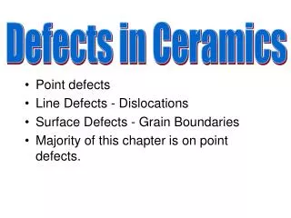
Defects in Ceramic Structures Shottky Defect: Frenkel Defect • Frenkel Defect --a cation is out of place. • Shottky Defect --a paired set of cation and anion vacancies.
Impurities + - Na Cl cation vacancy 2+ Ca + Na + Na 2+ Ca 2+ initial geometry Ca impurity resulting geometry • Substitutional anion impurity an ion vacancy 2- O - - Cl Cl 2- initial geometry O impurity resulting geometry • Impurities must also satisfy charge balance = Electroneutrality • Ex: NaCl • Substitutional cation impurity
Ceramic Phase Diagrams
Ternary phase diagram 34% Al2O3 45% SiO2
General properties of ceramics • Brittle (very low fracture toughness) • Better strength under compressive • Flexural strength is the rupture strength achieved from bending test • Creep occurs at higher temperature than metal (compressive) • Almost good hardness (used as abrasive materials) • A little plastic deformation may be observed in crystalline ceramics; slip plane • Non-crystalline ceramics; viscous flow • Porosity in ceramics decreases the modulus of elasticity and strength • High chemical durability
Mechanical Properties We know that ceramics are more brittle than metals. Why? • Consider method of deformation • slippage along slip planes • in ionic solids this slippage is very difficult • too much energy needed to move one anion past another anion • Higher strength under compressive stress • Generally utilized when load conditions are compressive
Measuring Elastic Modulus F cross section L/2 L/2 d R b δ= midpoint rect. circ. deflection • Determine elastic modulus according to: F 3 3 F L F L = = E x 3 4 d d p F 4 bd 12 R slope = rect. circ. d cross cross d section section linear-elastic behavior • Room T behavior is usually elastic, with brittle failure. • 3-Point Bend Testing often used. --tensile tests are difficult for brittle materials.
Measuring Strength F cross section L/2 L/2 d R b location of max tension δ = midpoint rect. circ. deflection s Material (MPa) E(GPa) fs Si nitride Si carbide Al oxide glass (soda) 250-1000 100-820 275-700 69 304 345 393 69 F x Ff d d fs • 3-point bend test to measure room T strength. • Typ. values: • Flexural strength: 3Ff L Ff L s = = fs 2bd2 pR3 Cir. Rect.
Measuring Elevated T Response • Elevated Temperature Tensile Test (T > 0.4 Tm). creep test e s x . e = steady-state creep rate slope = ss s time
Summary • Ceramic materials have covalent & ionic bonding. • Structures are based on: -- charge neutrality -- maximizing # of nearest oppositely charged neighbors. • Structures may be predicted based on: -- ratio of the cation and anion radii. • Defects -- must preserve charge neutrality -- have a concentration that varies exponentially w/T. • Room T mechanical response is elastic, but fracture is brittle, with negligible deformation. • Elevated T creep properties are generally superior to those of metals (and polymers).