Download
1 / 8
90 likes | 99 Views
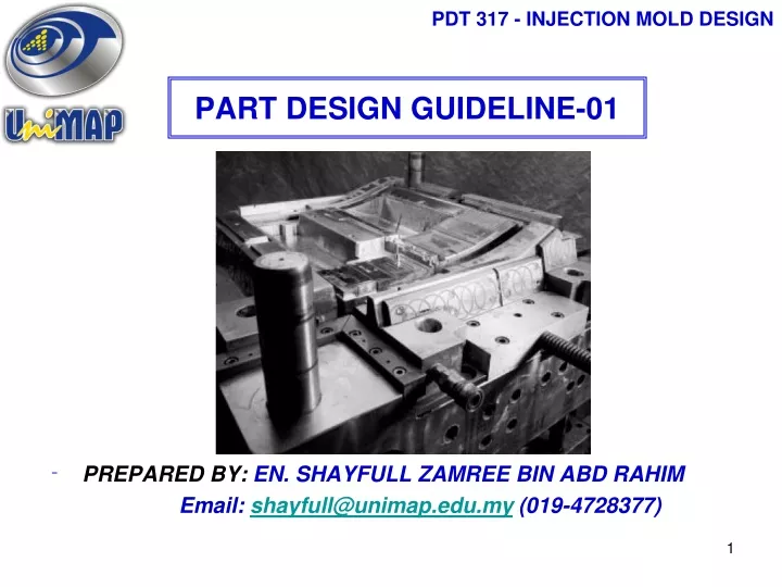
PDT 317 - INJECTION MOLD DESIGN. PART DESIGN GUIDELINE-01. PREPARED BY: EN. SHAYFULL ZAMREE BIN ABD RAHIM Email: shayfull@unimap.edu.my (019-4728377). PDT 317 - INJECTION MOLD DESIGN. COURSE CONTENT & COURSE OUTCOMES.

E N D
PDT 317 - INJECTION MOLD DESIGN PART DESIGN GUIDELINE-01 • PREPARED BY: EN. SHAYFULL ZAMREE BIN ABD RAHIM Email: shayfull@unimap.edu.my (019-4728377)
PDT 317 - INJECTION MOLD DESIGN COURSE CONTENT & COURSE OUTCOMES CO2: Ability to define and describe the procedure of designing plastic products for injection moulding process.
PDT 317 - INJECTION MOLD DESIGN UNIFORM WALL THICKNESS • The typical plastic part may be considered to have a shell type • configuration with a basic surface and features which are • attached to it to meet functional requirements.
PDT 317 - INJECTION MOLD DESIGN UNIFORM WALL THICKNESS Uniform Wall Thickness
PDT 317 - INJECTION MOLD DESIGN UNIFORM WALL THICKNESS “Transition should be made gradually, on the order of 3 to 1.”
PDT 317 - INJECTION MOLD DESIGN Part Design Guideline The actual determination of the “wall thickness” is based on a number of considerations. These include: • Application Requirements. Structural requirements including strength, impact, fatigue or deflection will be influenced by the wall thickness selected. Electrical loads may also impact on the wall thickness. • Moldability. The size of the part and the ability of the material to fill the furthest point can determine the minimum wall. The maximum flow length is also a function of tool design with gate location and number of gates used. • Agency requirements. For some agency properties, the rating is based on a minimum wall thickness which the part design must meet or exceed to satisfy an agency requirement. This would be the case for UL flammability or RTI.
PDT 317 - INJECTION MOLD DESIGN SEKIANTERIMA KASIH