Download
1 / 36
360 likes | 434 Views
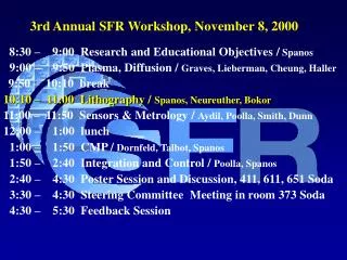
3rd Annual SFR Workshop & Review, May 24, 2001. 8:30 – 9:00 Research and Educational Objectives / Spanos 9:00 – 9:45 CMP / Doyle, Dornfeld, Talbot, Spanos 9:45 – 10:30 Plasma & Diffusion / Graves, Lieberman, Cheung, Haller 10:30 – 10:45 break

E N D
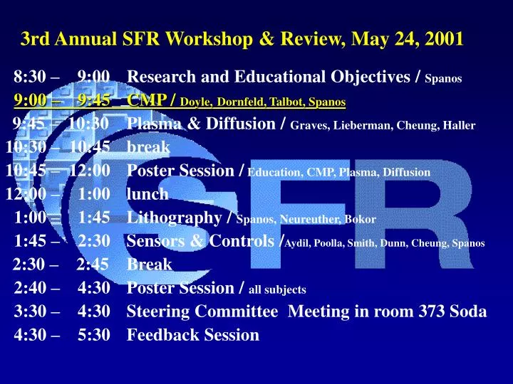
3rd Annual SFR Workshop & Review, May 24, 2001 8:30 – 9:00 Research and Educational Objectives / Spanos 9:00 – 9:45 CMP / Doyle,Dornfeld, Talbot, Spanos 9:45 – 10:30 Plasma & Diffusion / Graves, Lieberman, Cheung, Haller 10:30 – 10:45 break 10:45 – 12:00 Poster Session / Education, CMP, Plasma, Diffusion 12:00 – 1:00 lunch 1:00 – 1:45 Lithography / Spanos, Neureuther, Bokor 1:45 – 2:30 Sensors & Controls /Aydil, Poolla, Smith, Dunn, Cheung, Spanos 2:30 – 2:45 Break 2:40 – 4:30 Poster Session / all subjects 3:30 – 4:30 Steering Committee Meeting in room 373 Soda 4:30 – 5:30 Feedback Session
Chemical Mechanical Planarization SFR Workshop & Review May 24, 2001 David Dornfeld, Fiona Doyle, Costas Spanos, Jan Talbot Berkeley, CA
CMP Milestones • September 30th, 2001 • Build integrated CMP model for basic mechanical and chemical elements. Develop periodic grating metrology (Dornfeld, Doyle, Spanos ,Talbot). Model Outline Progressing- initial Chemical and Mechanical Modules in Development • September 30th, 2002 • Integrate initial chemical models into basic CMP model. Validate predicted pattern development. (Dornfeld, Doyle, Spanos ,Talbot) . • September 30th, 2003 • Develop comprehensive chemical and mechanical model. Perform experimental and metrological validation. (Dornfeld, Doyle, Spanos, Talbot)
Abstract 2002 Milestone: Integrate initial chemical models into basic CMP model. Validate predicted pattern development. Key areas involved in this are: • Chemical Aspects of CMP (Talbot and Gopal) • Glycine effects on CMP & chemical effect on abrasion (Doyle and Asku) • Material Removal in CM P: Effects of Abrasive Size Distribution and Wafer-Pad Contact Area (Dornfeld and Luo) • Fluid/Slurry Flow Analysis for CMP Model (Dornfeld and Mao) • Fixed Abrasive Design for C MP (Dornfeld and Hwang) • CMP Process Monitoring using Acoustic Emission (Dornfeld and Chang) • Establishing full-profile metrology for CMP modeling (Spanos and Chang) Recent activities in yellow will be reviewed here
Overview X X
Model development scenario • Identify key influences of chemical and mechanical activity • Experimental analysis of influences in parallel with model formulation for “module” development • Identification of “coupling” elements of mechanical and chemical activity • Build “coupling” elements into integrated model • Full scale model verification by simulation and test • Strategies for model-based process optimization
Focus of this presentation • Review of progress in understanding the role of chemistry in CMP • Update on process monitoring activity • Full-profile metrology for CMP modeling • Details of these and other key areas in posters
Slurry Concentration, Abrasive Shape,Density, Size and Distribution Down Pressure PadRoughness Wafer, Pattern,Pad and Polishing Head Geometry and Material Pad Hardness Relative Velocity SlurryChemicals Chemical Reaction Model (RR0)chem Contact Pressure Model Model of Active Abrasive Number N Model of Material Removal VOL by a Single Abrasive Wafer Hardness Pressure and Velocity Distribution Model (FEA and Dynamics) Fluid Model Physical Mechanism; MRR: N´VOL Preston’s Coefficient Ke (RR0 )mech Dishing & Erosion WIWNU Surface Damage MRR WIDNU Review - Overview of Integrated Model WIWNU
Chemical Aspects of CMPRole of Chemistry • Chemical and electrochemical reactions between material (metal, glass) and constituents of the slurry (oxidizers, complexing agents, pH) • Dissolution and passivation • Solubility • Adsorption of dissolved species on the abrasive particles • Colloidal effects • Change of mechanical properties by diffusion & reaction of surface
Modeling of Chemical Effects • Electrochemical/chemical dissolution and passivation of surface constituents • Colloidal effects (adsorption of dissolved surface to particles or re-adsorption) • Solubility changes • Change of mechanical properties (hardness, stress)
Copper Interconnection using Chemical Mechanical Planarization (CMP)Fiona Doyle and Serdar Asku • How Glycine Changes Electrochemistry of Copper? • Comparison of Cu Behavior in Aqueous Solutions with and without Glycine in terms of • Potential-pH Diagrams • Polarization Experiments How Electrochemical Behavior Changes under Abrasion • In-situ Electrochemical Experiments during Polishing using Slurries/ Solutions with or without Glycine • In-situ Polarization Experiments • In-situ Monitoring of Open Circuit Potential (EOC) Conclusions Experimental Results and Their Comparison with the Theoretical Diagrams
DUAL DAMASCENE PROCESS Trench SiO2 SiN Etch Deposit Barrier Copper Fill CMP Via CHEMICAL MECHANICAL PLANARIZATION Slurry feeder Pressure ALUMINA PARTICLES w/ Average Size ~ 120 nm From EKC Tech. • SLURRY • Abrasive particles • Chemicals Carrier Wafer Rotation Patterned wafer Polishing Plate POLISHING PAD Cross-sectional View of SUBA 500 Pad, Rodel Corp. (Taken from Y. Moon’s PhD Thesis) Polishing pad Pad asperities Copper Interconnection with CMP
Objective and Methods In Copper CMP, Electrochemical and Mechanical Mechanisms are not Well Understood Slurries are formulated empirically at present • Develop a Fundamental Basis for the Behavior of • Slurries with Complexing Agents • Tertiary Potential-pH Diagrams • Polarization Experiments using Cu Rotating Disk Electrode • In-situ Electrochemical Experiments during Polishing
Rotating Cu Disk electrode Fritted glass gas bubbler Experimental Techniques Rotating Disk Electrode Rotator Frame w Luggin Probe & Reference Electrode Slurry pool P Magnetic stirrer Pt Counter Electrodes Copper Working Electrode Polish pad In-situ Electrochemical Experiments
RDE 200 rpm Scan Rate 2 mV/sec pH and pH Buffer System EOC (mV vs. SHE) iOC (A/cm2) 4, With Acetate Buffer + 10-2 M Na2SO4 196 4.43x10⁻⁶ 9, With Carbonate Buffer + 10-2 M Na2SO4 102 3.23x10⁻⁶ 12, No Buffer 24 2.17x10⁻⁶ Cu-H2O System CuT=10-5
RDE 200 rpm Scan Rate 2 mV/sec 10-2 M Glycine pH and pH Buffer System EOC (mV vs. SHE) iOC (A/cm2) 4, With Acetate Buffer + 10-2 M Na2SO4 186 6.41x10⁻⁶ 9, No Buffer + 10-2 M Na2SO4 -26 1.04x10⁻⁵ 12, No Buffer -65 1.21x10⁻⁵ Cu-H2O-Glycine System CuT=10-5 ; LT=10-2
pH=9 pH=9 pH=10 pH=10 pH=11 pH=11 pH=12 pH=12 CuT=10-5 ; LT=10-2 CuT=10-4 ; LT=10-1 Cu-H2O-Glycine System (De-aerated)
No Glycine 10-2 M Glycine RDE/ IN-SITU 200 rpm 27.6 kPa Scan Rate 2 mV/s Chemical Composition Abrasion Type EOC (mV vs. SHE) iOC (A/cm2) Acetate Buffer 10-2 M Na2SO4 No Glycine No abrasion (RDE) 196 4.43x10⁻⁶ Polishing w/ pad only 191 4.69x10⁻⁶ Polishing w/ pad + 5wt % Al2O3 188 6.18x10⁻⁶ Acetate Buffer 10-2 M Na2SO4 10-2 M glycine No abrasion 186 6.41x10⁻⁶ Polishing w/ pad only 183 7.33x10⁻⁶ Polishing w/ pad + 5wt % Al2O3 181 1.16x10⁻⁵ In-Situ Polarization at pH=4
No Glycine 10-2 M Glycine RDE/ IN-SITU 200 rpm 27.6 kPa Scan Rate 2 mV/s Chemical Composition Abrasion Type EOC (mV vs. SHE) iOC (A/cm2) Carbonate Buffer 10-2 M Na2SO4 No Glycine No abrasion (RDE) 102 3.23x10⁻⁶ Polishing w/ pad only 92 5.18x10⁻⁶ Polishing w/ pad + 5wt % Al2O3 46 4.09x10⁻⁵ No Buffer 10-2 Na2SO4 10-2 M glycine No abrasion -26 1.04x10⁻⁵ Polishing w/ pad only -32 1.28x10⁻⁵ Polishing w/ pad + 5wt % Al2O3 -33 2.87x10⁻⁵ In-Situ Polarization at pH=9
No Glycine 10-2 M Glycine RDE/ IN-SITU 200 rpm 27.6 kPa Scan Rate 2 mV/s Chemical Composition Abrasion Type EOC (mV vs. SHE) iOC (A/cm2) No Buffer/Na2SO4 DD Water with No Glycine No abrasion (RDE) 23 2.17x10⁻⁶ Polishing w/ pad only 12 4.83x10⁻⁶ Polishing w/ pad + 5wt % Al2O3 -140 9.72x10⁻⁶ No Buffer No Na2SO4 10-2 M glycine No abrasion -68 1.21x10⁻⁵ Polishing w/ pad only -75 3.42x10⁻⁵ Polishing w/ pad + 5wt % Al2O3 -163 8.62x10⁻⁵ In-Situ Polarization at pH=12
In-Situ OC Potential Measurements Without Glycine With 10-2 M Glycine
Conclusions • Polarization results well correlated with potential-pH diagrams • No significant changes in in-situ polarization for active behavior • Mechanical components significantly affected in-situ polarization • for active-passive behavior • Kaufman’s tungsten CMP model is also valid for Cu CMP • Glycine (complexing agents) may enhance the polishing efficiency.
Future Work-I Determination of Chemical (Electrochemical) and Mechanical Contributions • Maintain a Constant Level Of In-Situ Polarization, Measure Current • CHEMICAL CONTRIBUTION from Time-Averaged Current • POLISH RATE from Weight Loss • MECHANICAL CONTRIBUTION from the Difference Generation of Chemical,Mechanical and Total Removal Rate versus Polarization Plots at Different pH’s.
Future Work-II In-Situ Electrochemical Experiments using “Patterned” Cu Electrodes • In-Situ Polarization Experiments • Polishing at a Constant Level of Polarization • Surface Examination of Passive Films XPS, Auger Spectroscopy Verification of Kaufman’s Model using “Patterned” Cu Electrodes
Process Monitoring of CMP using Acoustic EmissionAndrew Chang UCBMotivation • Endpoint Detection • The characteristics of the acoustic emission signal from various materials can be easily discernable during the polishing process. • Outside noise sources, once characterized, can be minimized and filtered from disturbing the process signal. • Scratch Detection • Scratches and/or other mechanically induced flaws (large agglomeration of particles, contaminants on the pad, etc.) can be detected and used as feedback for purposes of real-time process control. • Abrasive Slurry Design • Energy of the AE signal can be correlated to the active number of abrasive particles during polishing for slurry concentration optimization
Acoustic Emission Propagation in the Wafer Schematic view of abrasive particles during polishing (exaggerated view) Sensor Wafer Oil film couplant Wafer carrier Carrier ring Abrasives in slurry Pad Polishing plate Individual burst emission waves generated by abrasive particles contacting wafer produce a continuous acoustic emission source. Wafer
CMP Tool Toyoda Float Polishing Machine Test Wafers Bare silicon & copper blanket wafers Slurry type ILD 1300, abrasive size (~100 nm) Alumina slurry, abrasive size (~100 nm) Pad type IC 1000/Suba IV stacked pad Polishing Conditions Pressure = ~ 1 psi Table Speed = 50 RPM Wafer Carrier Speed = Stationary Slurry flowrate = 150 ml/min Experimental Setup Pre-amplification & Primary amplification PC Data Acquisition Raw AE Signal Conditioning (60-100 dB) Raw Sampling Rate = 2 MHz
Raw Acoustic Emission from CMP Process Low frequency noise due vibrations from table motor, pad pattern effects, etc. Filtered raw signal containing high frequency AE content
Establishing full-profile metrology for CMP modeling Costas Spanos & Tiger Chang UCB • Use scatterometry to monitor the profile evolution • The results can be used for better CMP modeling Oxide Substrate
Mask Designed to explore Profile as a function of pattern density • The size of the metrology cell is 250m by 250m • Periodic pattern has 2m pitch with 50% pattern density
Sensitivity of Scatterometry (GTK simulation) • We simulated 1 mm feature size, 2 mm pitch and 500nm initial step height, as it polishes. • The simulation shows that the response difference was fairly strong and detectable.
Wafer # Down Force (psi) Table Speed (rpm) Slurry Flow (ml/min) 1 4 40 50 2 8 40 50 3 4 40 150 4 8 40 150 5 8 80 50 6 4 80 50 7 8 80 150 8 4 80 150 9 6 60 100 10 6 60 100 11 6 60 100 Characterization Experiments Completed • Three one-minute polishing steps were done using the DOE parameters Initial profiles Sopra/AFM Wafer cleaning Nanospec Thickness measurement CMP Sopra Spectroscopic ellipsometer AFM (AMD/SDC)
C D E A oxide B Substrate Library-based Full-profile CMP Metrology Five variables were used in to generate the response library: bottom oxide height (A), bottom width (B), slope 1 (C), slope 2 (D) and top oxide height (E). Reference: X. Niu, N. Jakatdar, J. Bao, C. Spanos, S. Yedur, “Specular spectroscopic scatterometry in DUV lithography”, Proceedings of the SPIE, vol.3677, pt.1-2, March 1999.
Scatterometry AFM SEM Full Profile CMP Results, so far • Extracted profiles match SEM pictures within 10nm • Scatterometry is non-destructive, faster and more descriptive than competing methods. • Next challenge: explore application in wet samples.
Conclusions • Chemical effectsmodel and synergy with mechanical effects being developed and validated • Mechanical effects model validated for abrasive size and activity and wafer-pad contract area • Fabrication technique for micro-scale abrasive design experiments • Sensing system for process monitoring and basic process studies being validated • Scatterometry metrology sensitivity study indicates suitability for observing profile evolution
2002 & 2003 Goals Develop comprehensive chemical and mechanical model. Perform experimental and metrological validation, by 9/30/2003. • Simulation of Integrated CMP model • Experimental verification of integrated CMP model (role of chemistry elements, mechanical elements in mechanical material removal)