Download
1 / 1
10 likes | 111 Views
Use of a 3-layer Control System for Non-Destructive Beam Probe Monitor. Photo camera. Investigated bunch. Phosphor screen. Deflector. MCP. D.Yu.Bolkhovityanov, D.A.Malyutin, A.A.Starostenko The Budker Institute of Nuclear Physics, Novosibirsk, Russia. data.

E N D
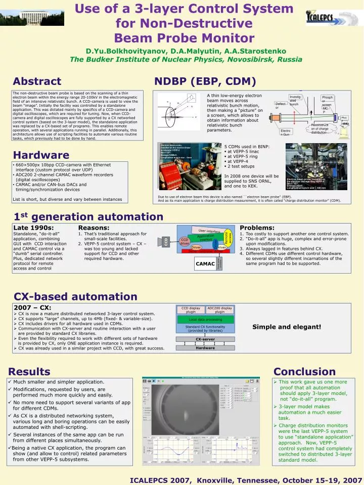
Use of a 3-layer Control Systemfor Non-DestructiveBeam Probe Monitor Photo camera Investigated bunch Phosphor screen Deflector MCP D.Yu.Bolkhovityanov, D.A.Malyutin, A.A.StarostenkoThe Budker Institute of Nuclear Physics, Novosibirsk, Russia data Reconstruction of charge distribution… Abstract NDBP (EBP, CDM) Electron Gun The non-destructive beam probe is based on the scanning of a thin electron beam within the energy range 20-100kV in the electromagnetic field of an intensive relativistic bunch. A CCD-camera is used to view the beam “image”. Initially the facility was controlled by a standalone application. This was dictated mainly by specifics of a CCD-camera and digital oscilloscopes, which are required for tuning. Now, when CCD-camera and digital oscilloscopes are fully supported by a CX networked control system (based on the 3-layer model), the standalone application was replaced by a CX-based set of programs. This enables remote operation, with several applications running in parallel. Additionally, this architecture allows use of scripting facilities to automate various routine tasks, which previously had to be done by hand. A thin low-energy electron beam moves across relativistic bunch motion, then making a “picture” on a screen, which allows to obtain information about relativistic bunch parameters. Electron beam probe, installed on the electron linear accelerator VEPP-5 Ne=1*1010 Energy=125MeV, Longitudinal bunch size ~ 6mm Electron beam probe, installed on the electron storage ring VEPP-4 Ne=1*1010 Energy=2GeV, Longitudinal bunch size ~ 100 mm • 5 CDMs used in BINP: • at VEPP-5 linac • at VEPP-5 ring • at VEPP-4 • 2 test setups • In 2008 one device will be supplied to SNS ORNL, and one to KEK. Hardware • 660×500px 10bpp CCD-camera with Ethernet interface (custom protocol over UDP) • ADC200 2-channel CAMAC waveform recorders (digital oscilloscopes) • CAMAC and/or CAN-bus DACs and timing/synchronization devices • List is short, but diverse and vary between instances Due to use of electron beam this device is also named ``electron beam probe'‘ (EBP). And as its main application is charge distribution measurement, it is often called “charge distribution monitor” (CDM). 1st generation automation Late 1990s: Standalone, “do-it-all”application, combiningGUI with CCD interaction and CAMAC control via a “dumb” serial controller. Plus, dedicated networkprotocol for remoteaccess and control Reasons: That’s traditional approach forsmall-scale facilities. VEPP-5 control system – CX –was too young and lackedsupport for CCD and otherrequired hardware. Problems: Too costly to support another one control system. “Do-it-all” app is huge, complex and error-proneupon modifications. Always lagged in features behind CX. Different CDMs use different control hardware,so several slightly different incarnations of thesame program had to be supported. CCD displayplugin ADC200 displayplugin User interface Remoteaccess Applicationintellect Local data processing CCDdriver CCD Driver Driver Driver Standard CX functionality(provided by libraries) Serial controller driver CAMAC CX-server Dumb serialcontroller Hardware CX-based automation • 2007 – CX: • CX is now a mature distributed networked 3-layer control system. • CX supports “large” channels, up to 4Mb (fixed- & variable-size). • CX includes drivers for all hardware used in CDMs. • Communication with CX-server and routine interaction with a user are provided by standard CX libraries. • Even the flexibility required to work with different sets of hardware is provided by CX, only ONE application instance is required. • CX was already used in a similar project with CCD, with great success. Simple and elegant! Results Conclusion • Much smaller and simpler application. • Modifications, requested by users, are performed much more quickly and easily. • No more need to support several variants of app for different CDMs. • As CX is a distributed networking system, various long and boring operations can be easily automated with shell-scripting. • Several instances of the same app can be run from different places simultaneously. • Being a native CX application, the program can show (and allow to control) related parameters from other VEPP-5 subsystems. • This work gave us one moreproof that all automation should apply 3-layer model, not “do-it-all” program. • 3-layer model makes automation a much easier task. • Charge distribution monitors were the last VEPP-5 system to use “standalone application” approach. Now, VEPP-5 control system had completely switched to distributed 3-layer standard model. ICALEPCS 2007, Knoxville, Tennessee, October 15-19, 2007